Blender Geometry Nodes
- v0.1
Today we will do a small starting experiment with Geometry Nodes. I’ll show what I do and explain what I can, and we’ll note the things we do not yet understand for further experimentation and study. In today’s starting exercise we will try to turn a mesh line into a circle. More or less.
Begin with a new blender file, with the standard cube. If you don’t have a cube, create one.
Select your cube and then select the geometry nodes layout at the top of the screen.

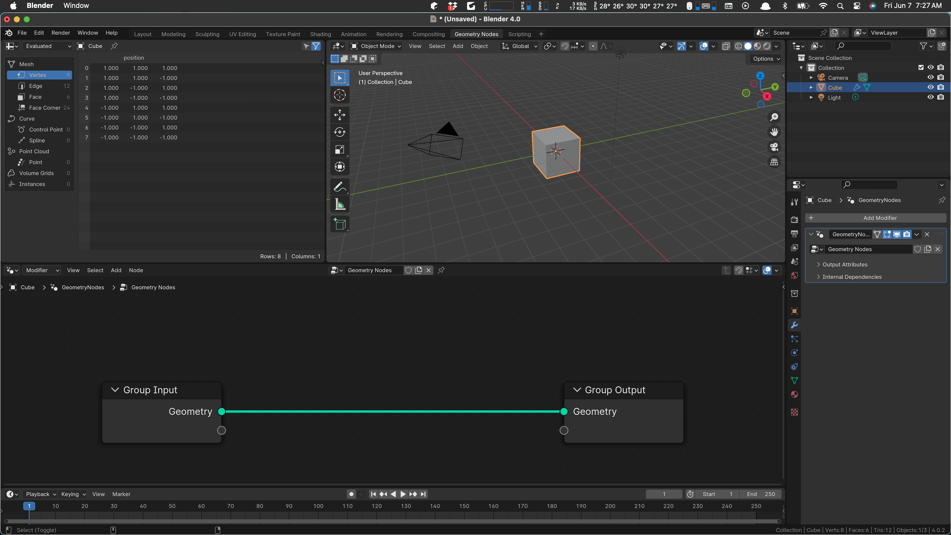
In the geometry panel at the bottom, click New. This adds a Geometry Nodes modifier to the cube. The screen now shows a “no-op” network, connecting geometry in with geometry out. I some magical way, the vertexes, edges, and faces of our input cube flow along the connection and, coming out the other end, they display in the scene.
If we disconnect the noodle (at least some people call the connections noodles), our cube will disappear from the scene. Disconnect it by dragging from the output end, just pulling the noodle off the connection. Your cube should disappear from the scene.
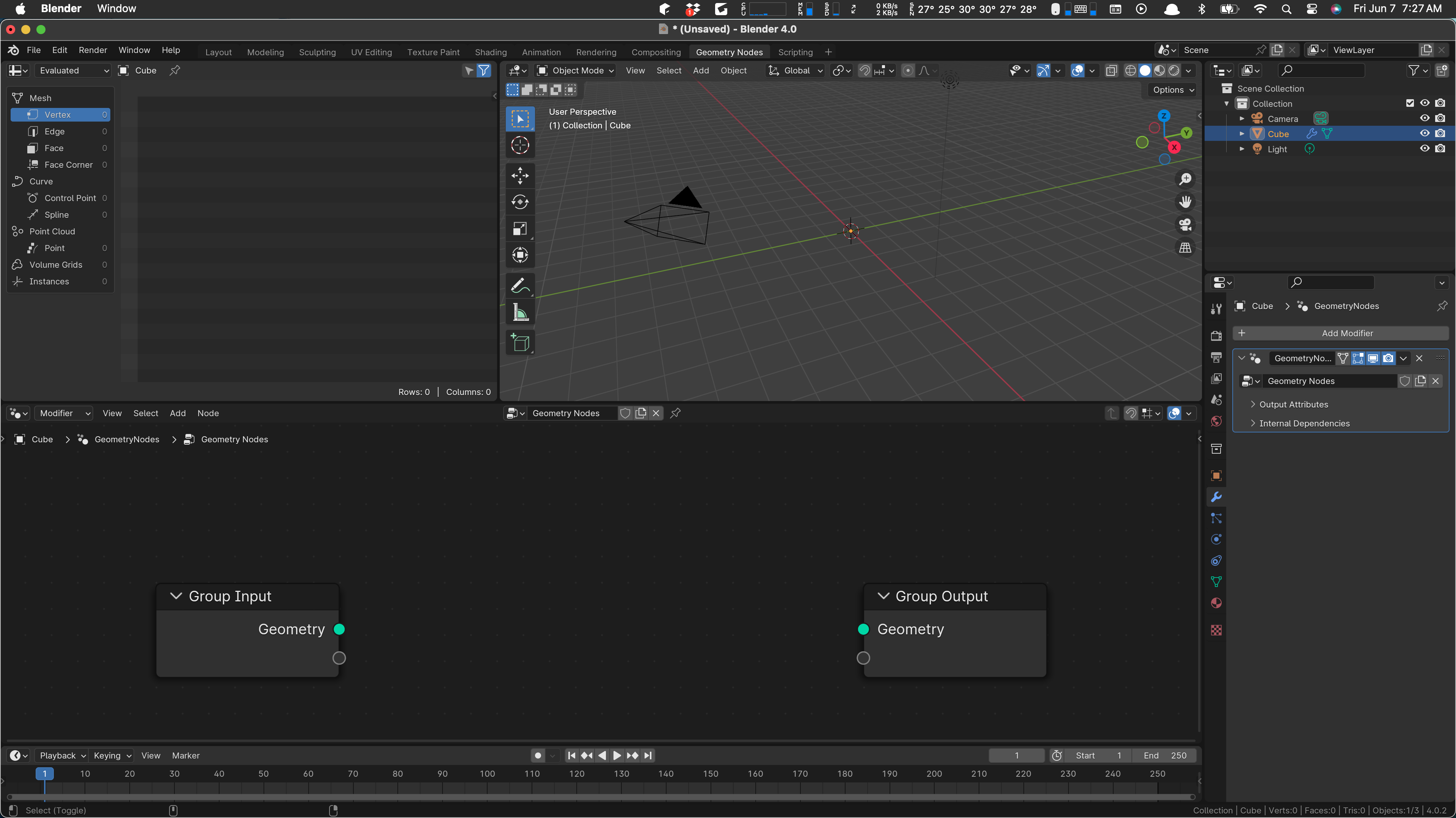
For practice pull a noodle from the input Geometry to the output and see that your cube appears again. Then pull the noodle away again: we are not going to use the cube at all. Doing this leaves the cube in our scene collection, but it has no geometry and will not display. I think we dare not remove it, because that will also remove what we are about to do.
There seem to be two basic ways of using geometry nodes. Sometimes you create an object in the scene and then modify it using nodes. Other times, you completely ignore the original object and create your own. That’s what we’re going to do now.
As with objects in the scene, we add geo nodes with Shift+A. If we type space immediately after that, we get a search field that is somewhat helpful in finding what we want. In this case we want to add a Mesh Line. I found that under Mesh / Primitives / Mesh Line After adding it, I hook the Mesh output of the line to the Geometry output, and our line appears:
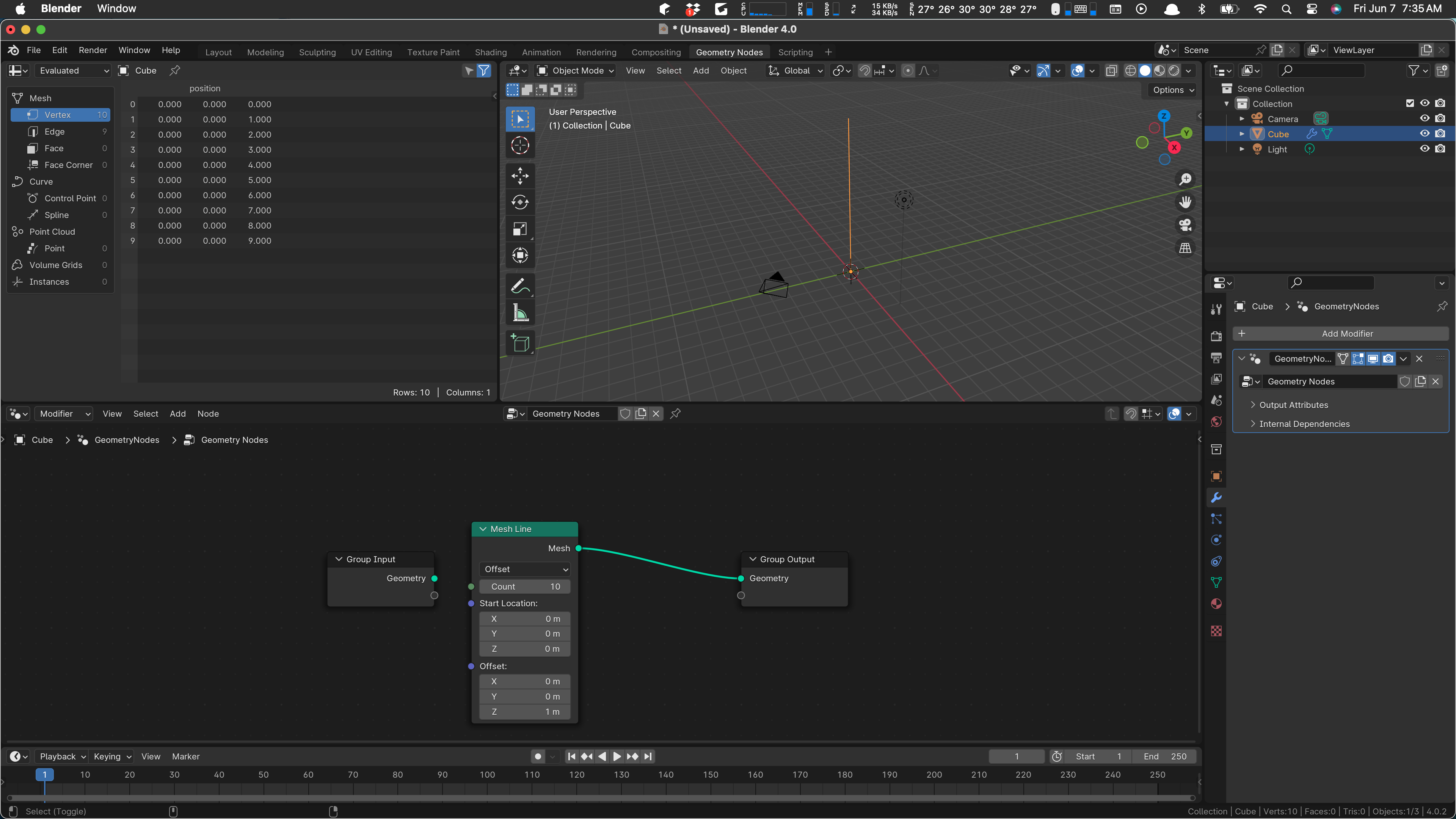
Notice the Count field. That tells us how many verts the line has. We can’t see them and in fact we can’t really even edit our line, because, so far, the geometry nodes are in a modifier, so the thing in the scene isn’t editable. If we were to apply our modifier, we’d have a “real” object and could further edit it. But that’s not why we’re here. We are here to convince this line that it is a circle, or at least as close to a circle as it can get.
What do we know about how to draw a circle? If we hearken back to our days in school, we may remember a couple of equations:
x squared plus y squared equals r squared
That one is probably familiar, the everyday Cartesian definition of a circle that you probably use almost every day.
Perhaps less familiar is this one:
r = k
In polar coordinates, no matter what value the angle part (theta) takes on, the radius of the point at that angle is always k, the desired radius of the circle. We’ll be using this idea, and also the two well-known (ha) definitions of x and y given a radius r and angle theta:
x = r * cos(theta)
y = r * sin(theta)
With luck, this will become somewhat more clear in a moment.
So … if we could iterate theta from zero to two pi (once around), and we could position our line’s vertices at x and y according to the rules above, we should get a circle. How many steps should we take from zero to two pi? We should take one step for each line segment in our mesh line. Since there are 10 verts, there are 9 steps after the first.
(I cannot explain this clearly but we need to use one less than the number of verts here.)
Anyway, what we’re going to do is to compute the position of x and y for each vert on our Mesh Line, set it to that position, and wire the result to our output geometry. So let’s put the final bits in now.
Now we need to compute our theta step, the angle that varies as we draw the circle, and then compute x and y.
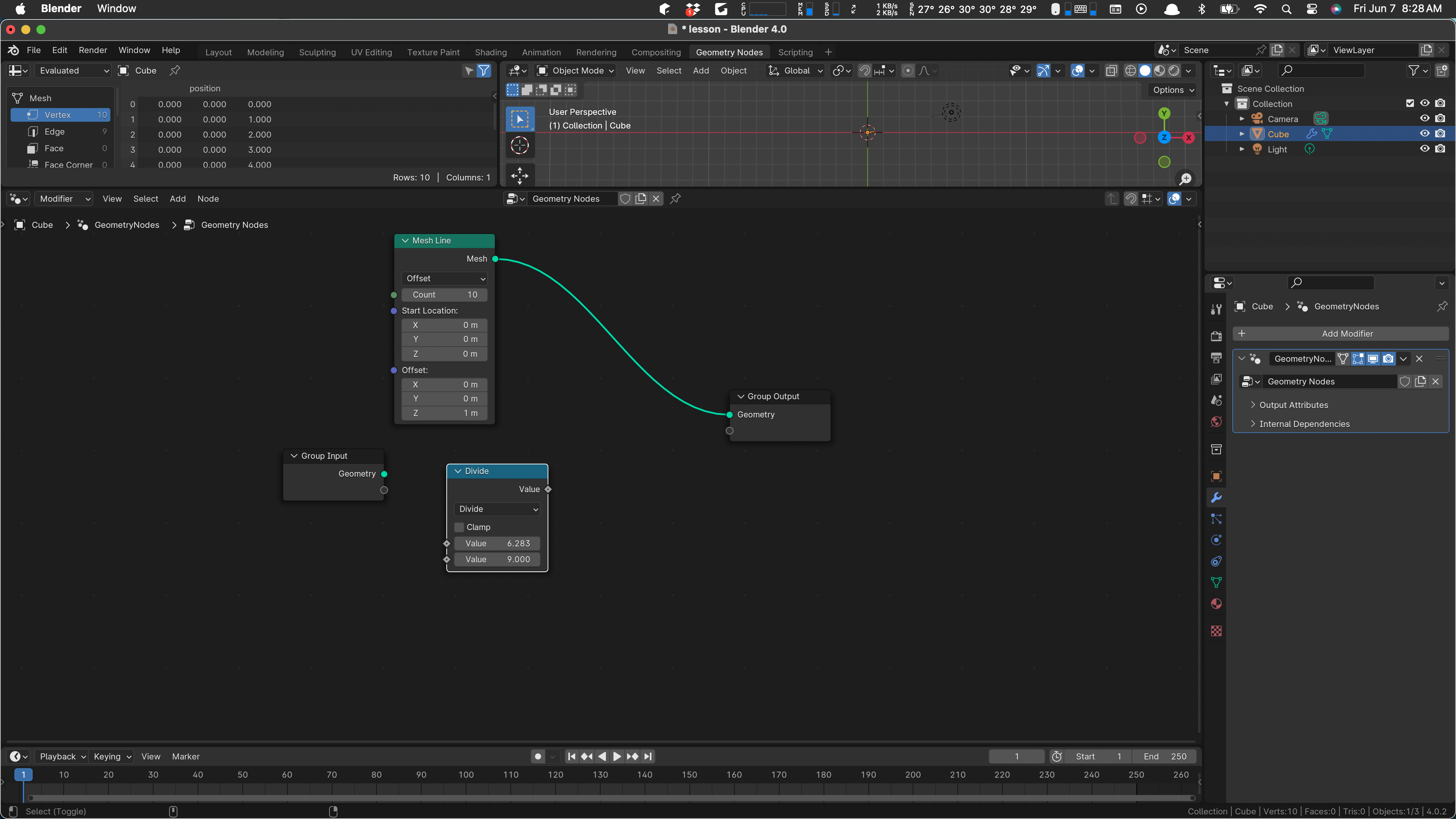
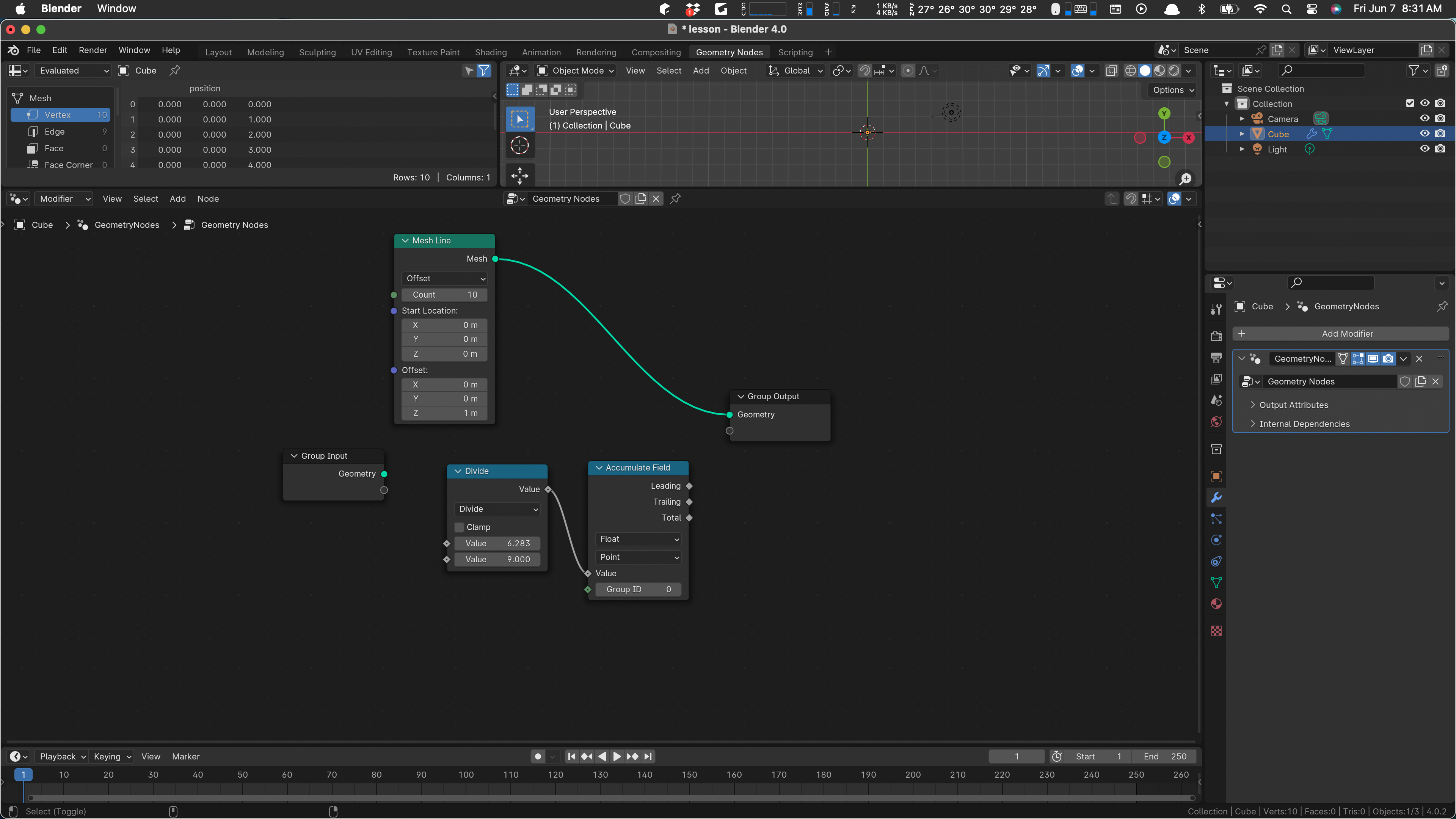
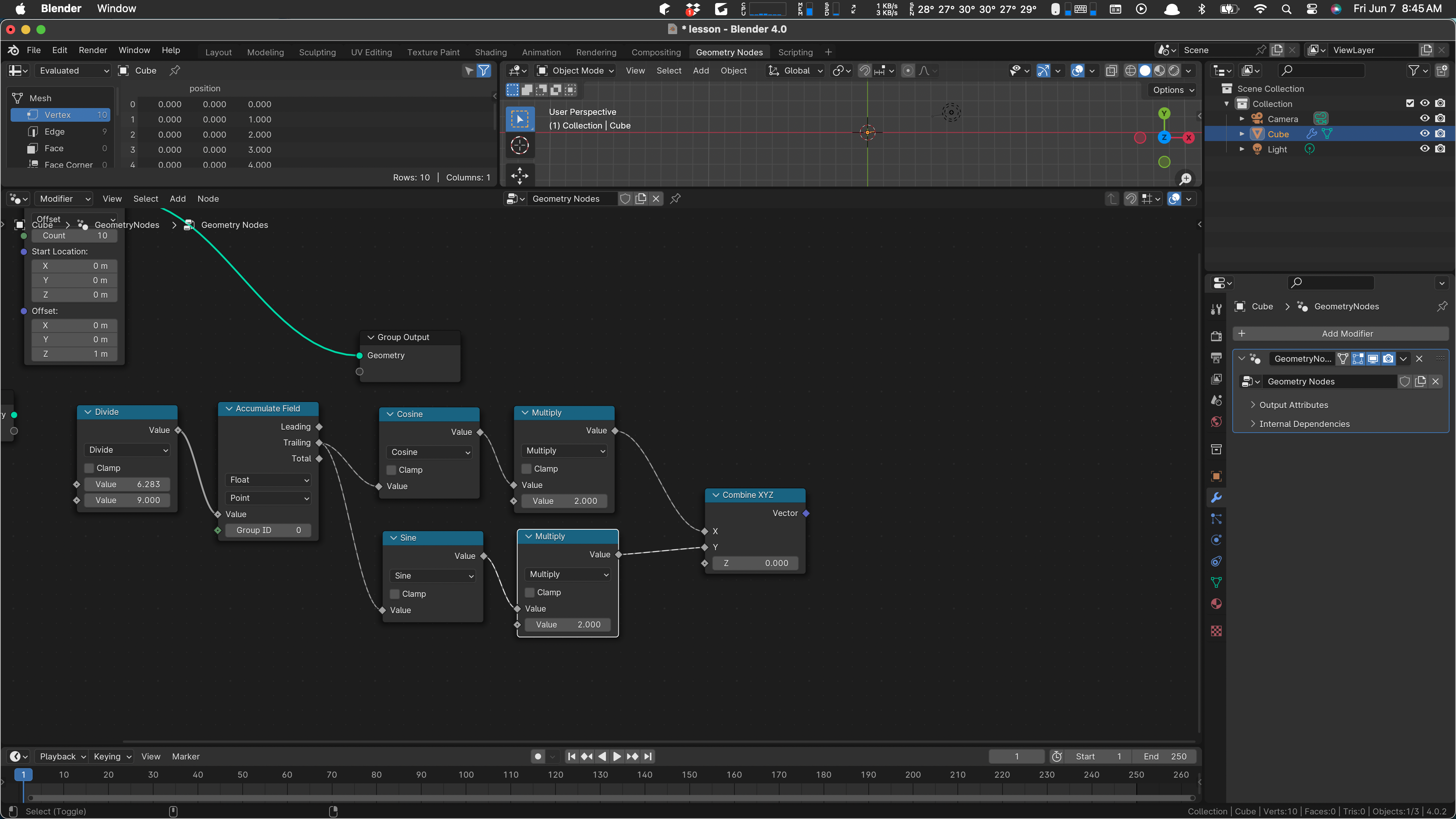
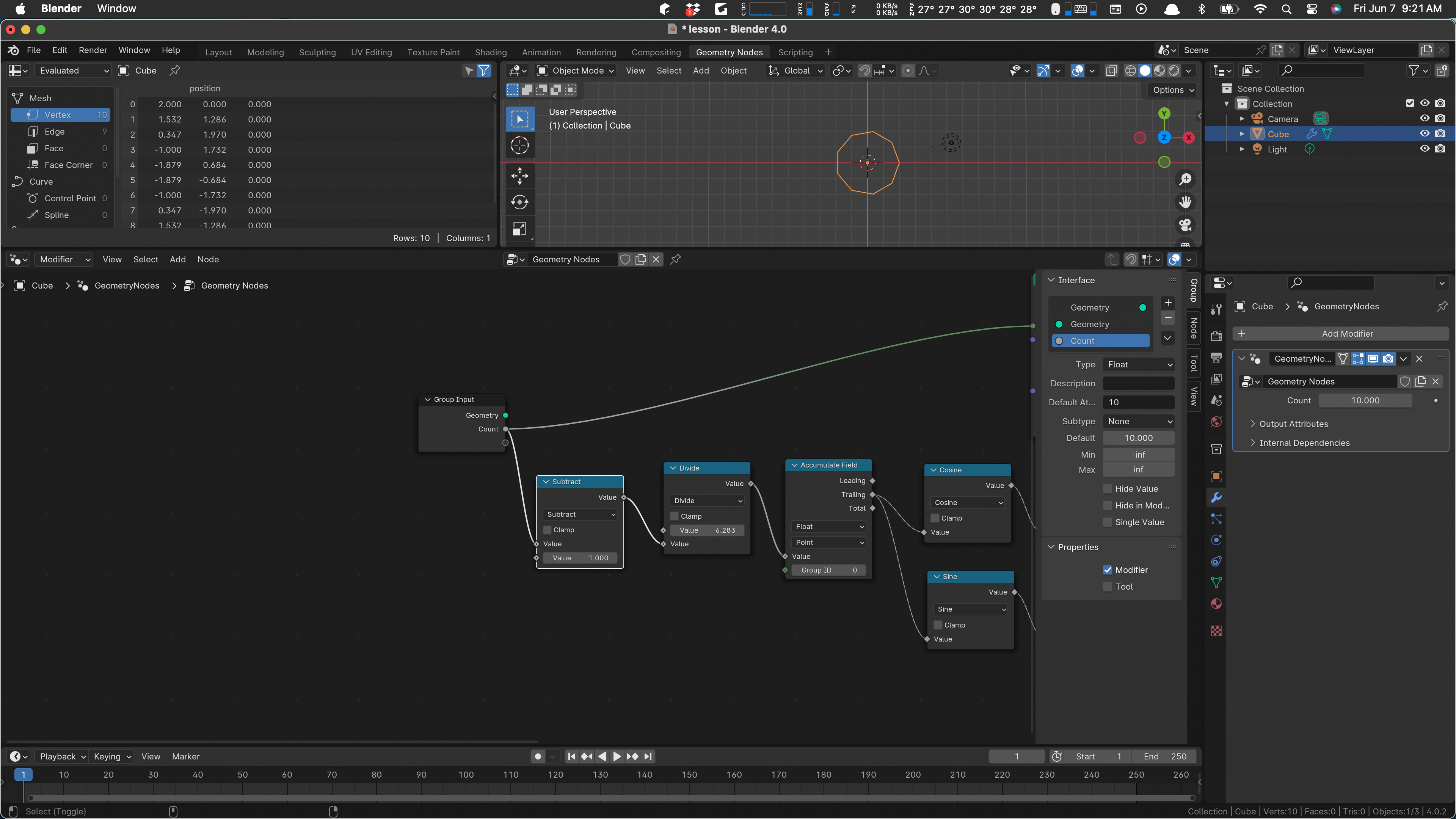
First add a Math node, a Divide. There is some short way to do that, but I don’t know it. So I add a math node and pull down on “add” to get “divide”. Anyway, we want to divide two pi by 9 (one less than the count on our mesh line). You can type 2*pi in the first value of the divide.
This is the step size once around over nine, so we need to accumulate that value, since each subsequent vertex wants the next value step, 2*step, 3*step and so on. Add an Accumulate Field and wire the output value of our divide to it:
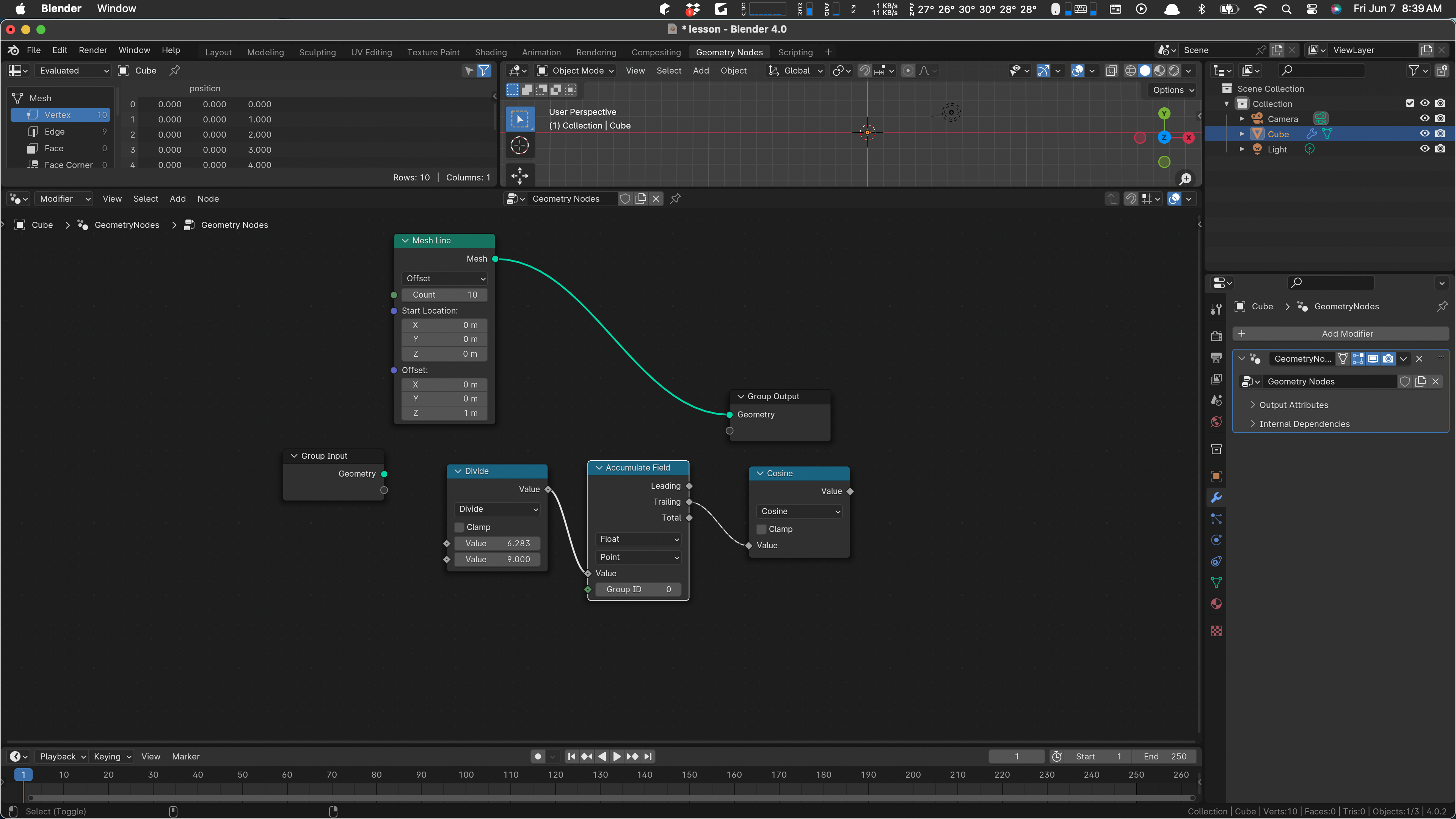
So the output of that node is our growing angle, step, 2*step, and so on. So from that we can compute x and y. Let’s use a radius of 2, just because.
x is r cosine theta, so add a math node for cosine. Wire the trailing value of the accumulate to the value input of the cosine:
Then wire in a multiply by two, because radius will be two The value of the cosine goes in one input and put 2.0 in the other value:
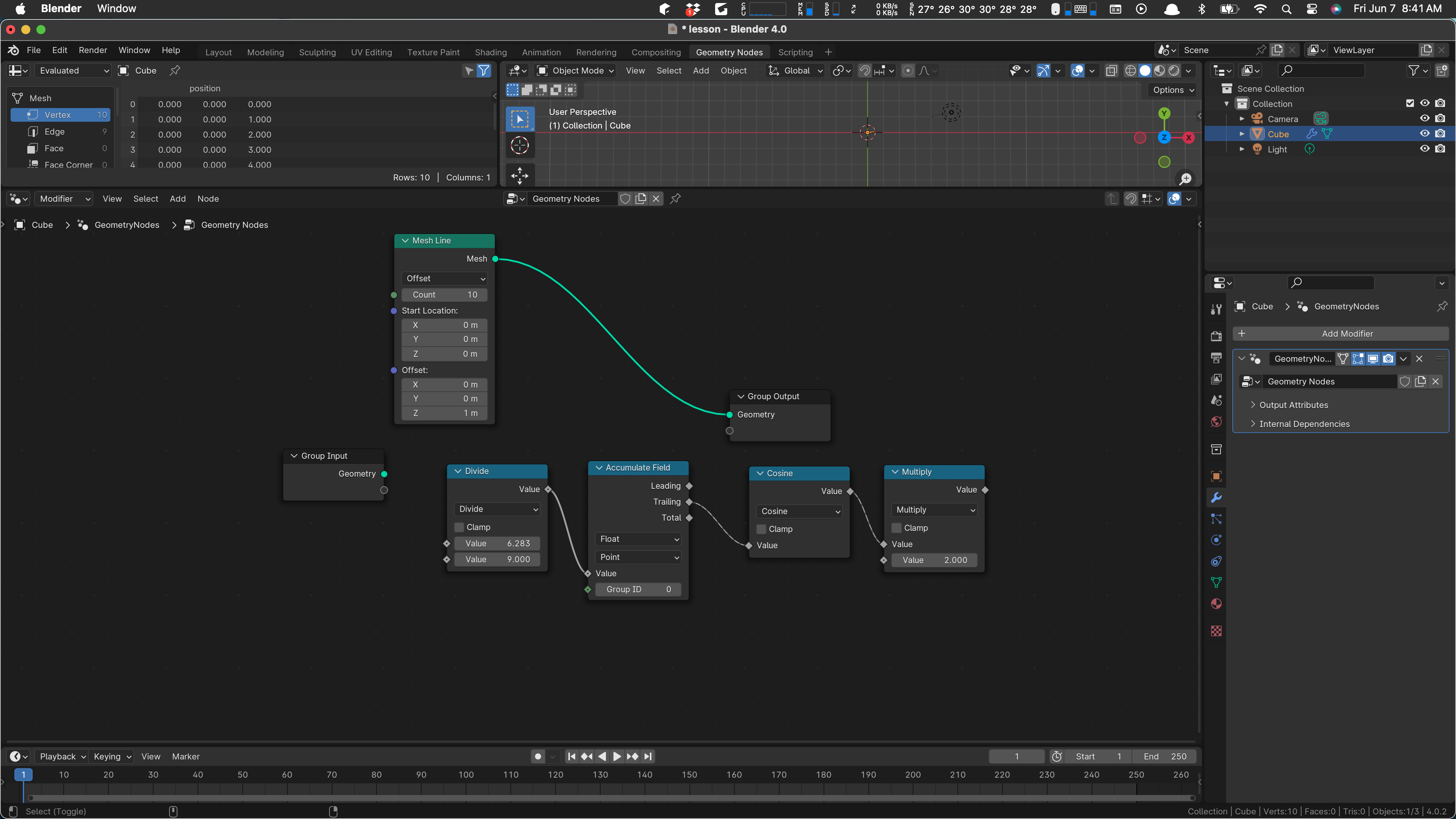
That’s our x value right there. We want the same thing except with sine. We can select those two nodes and Shift-D to duplicate and drag them down a bit:
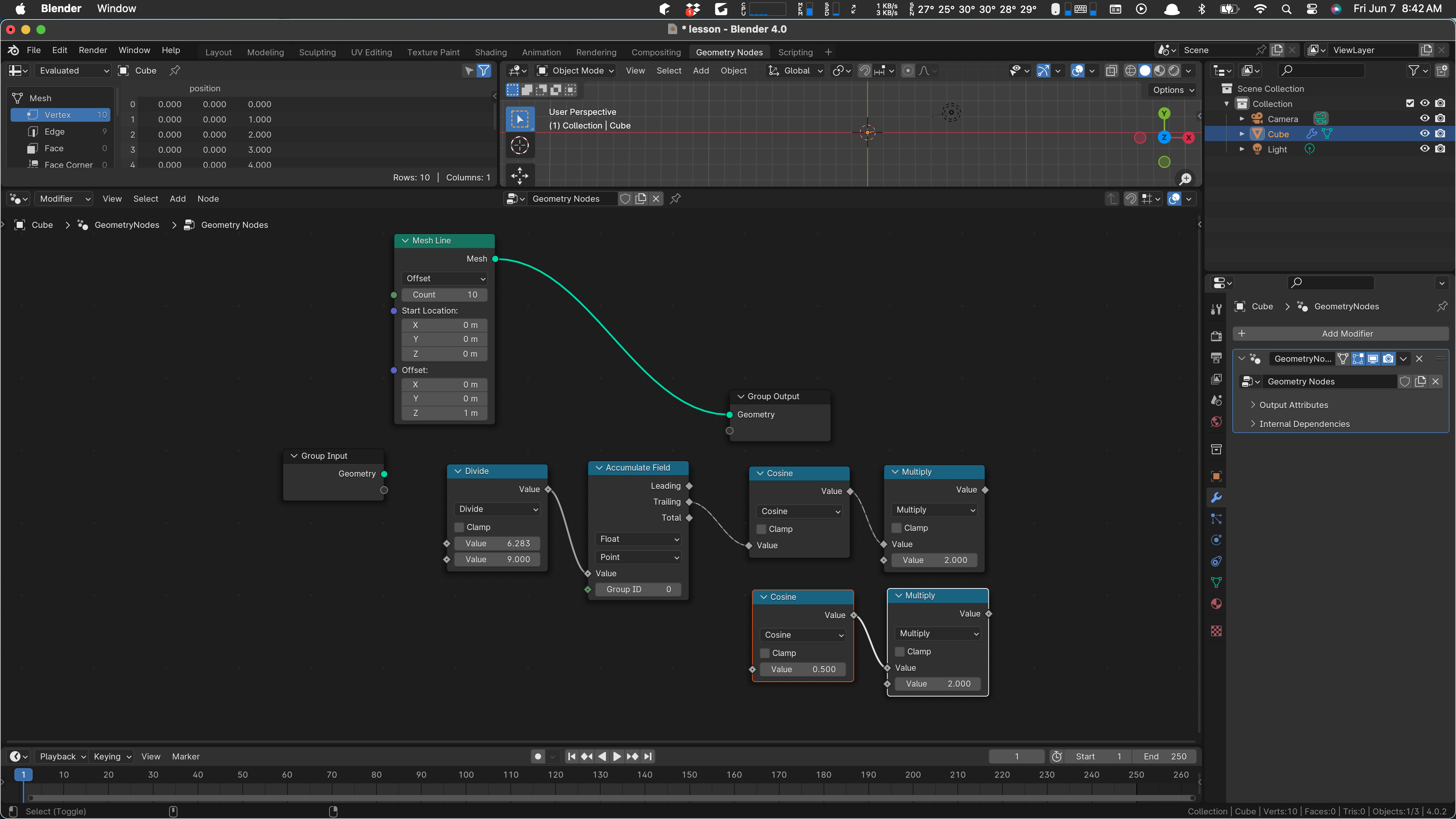
Change cosine to sine, and wire it in:

There’s our y. We just have to combine them, set position, and apply them to the geometry.
Add a Combine XYZ. (Searching for XYZ finds it easily.) Wire in the x and y:
We’ll leave z at zero and now we want to set the position. Somehow this knows to set the position of the vertex coming thru:
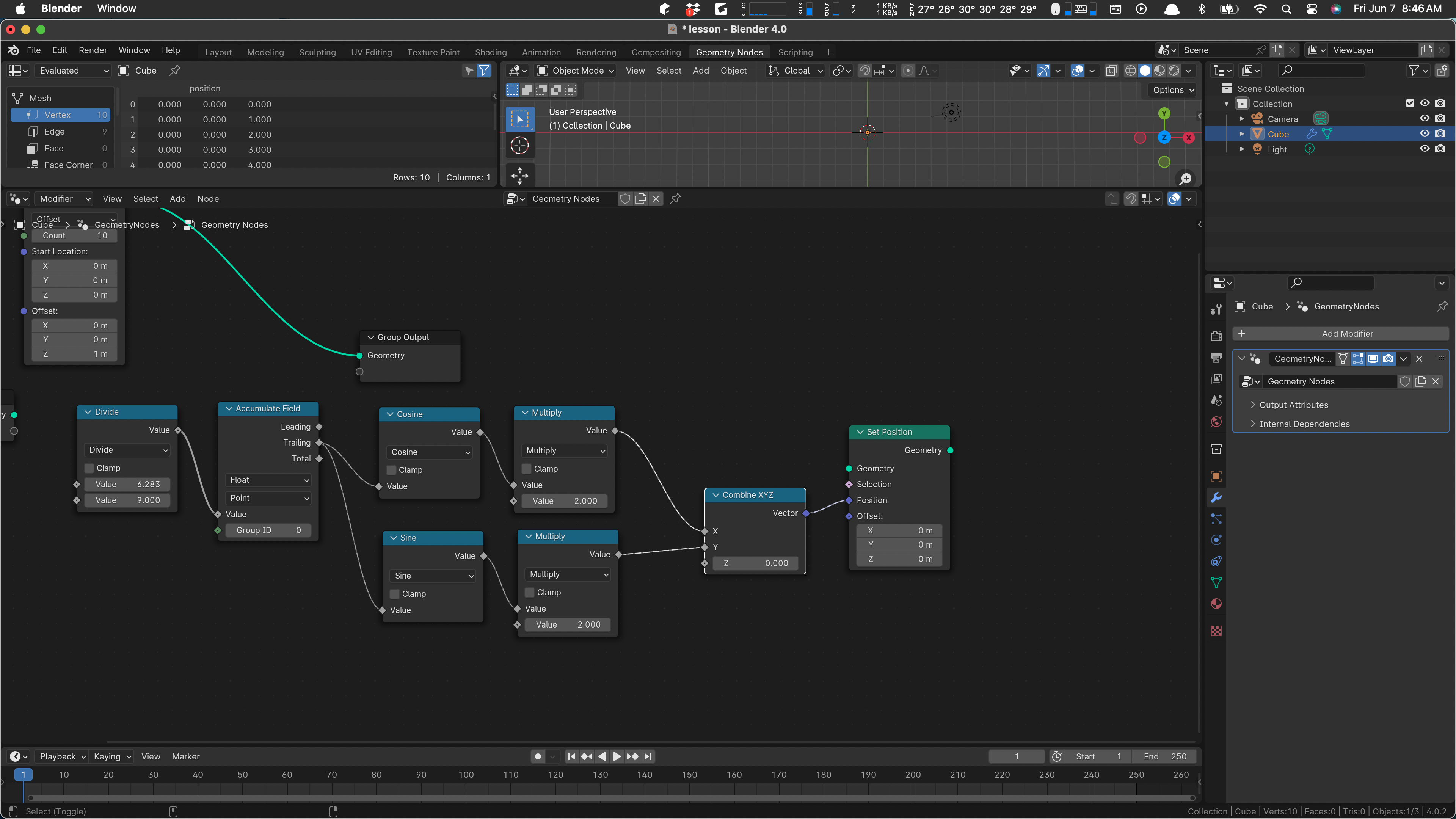
We’re basically done. All we need to do now is wire up the input geometry and hook to the output. Drag the output node over to get this:
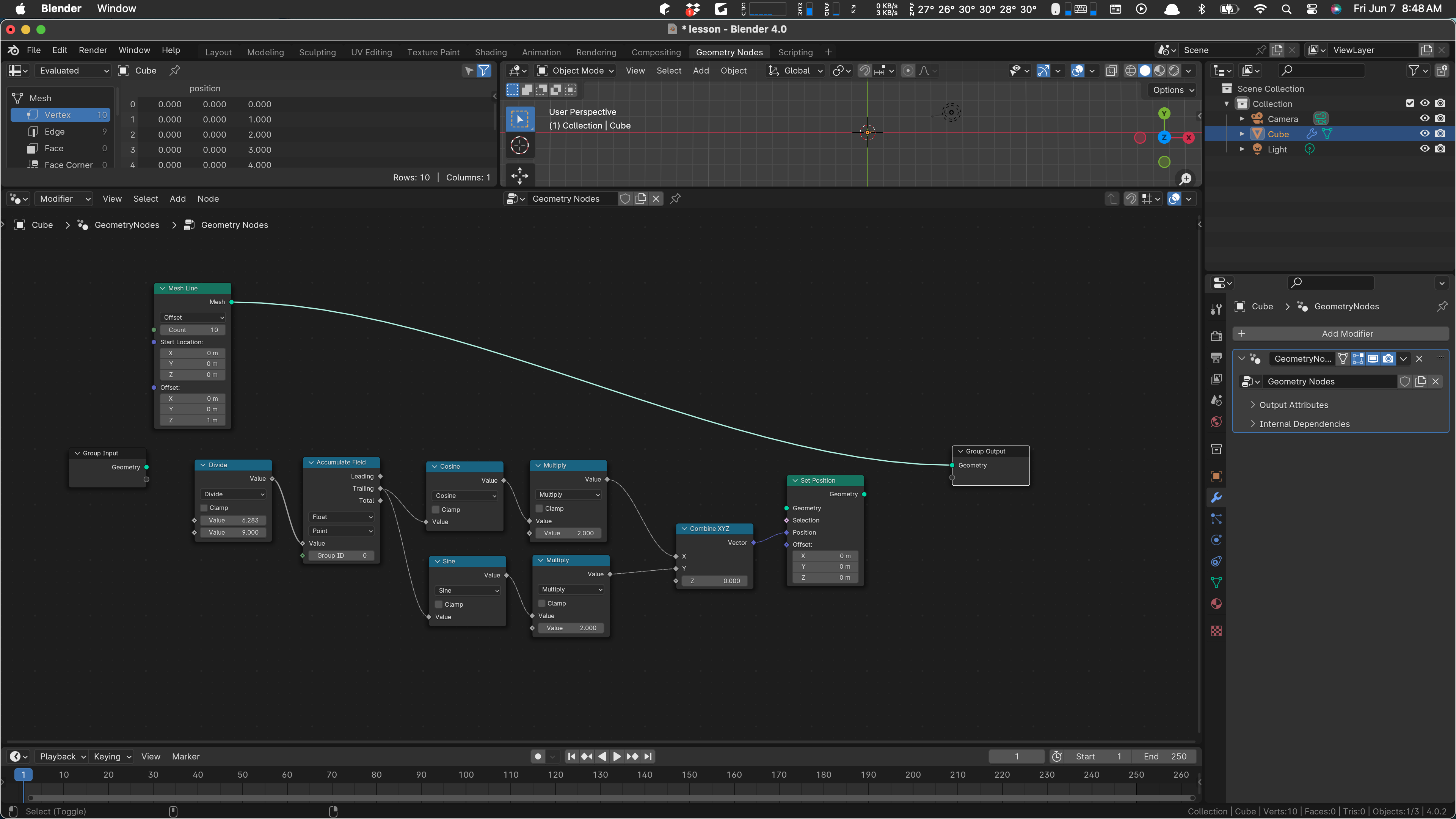
Then drag the geometry wire away from the output node, to the input geometry of the set position … and wire set position to the geometry output node:
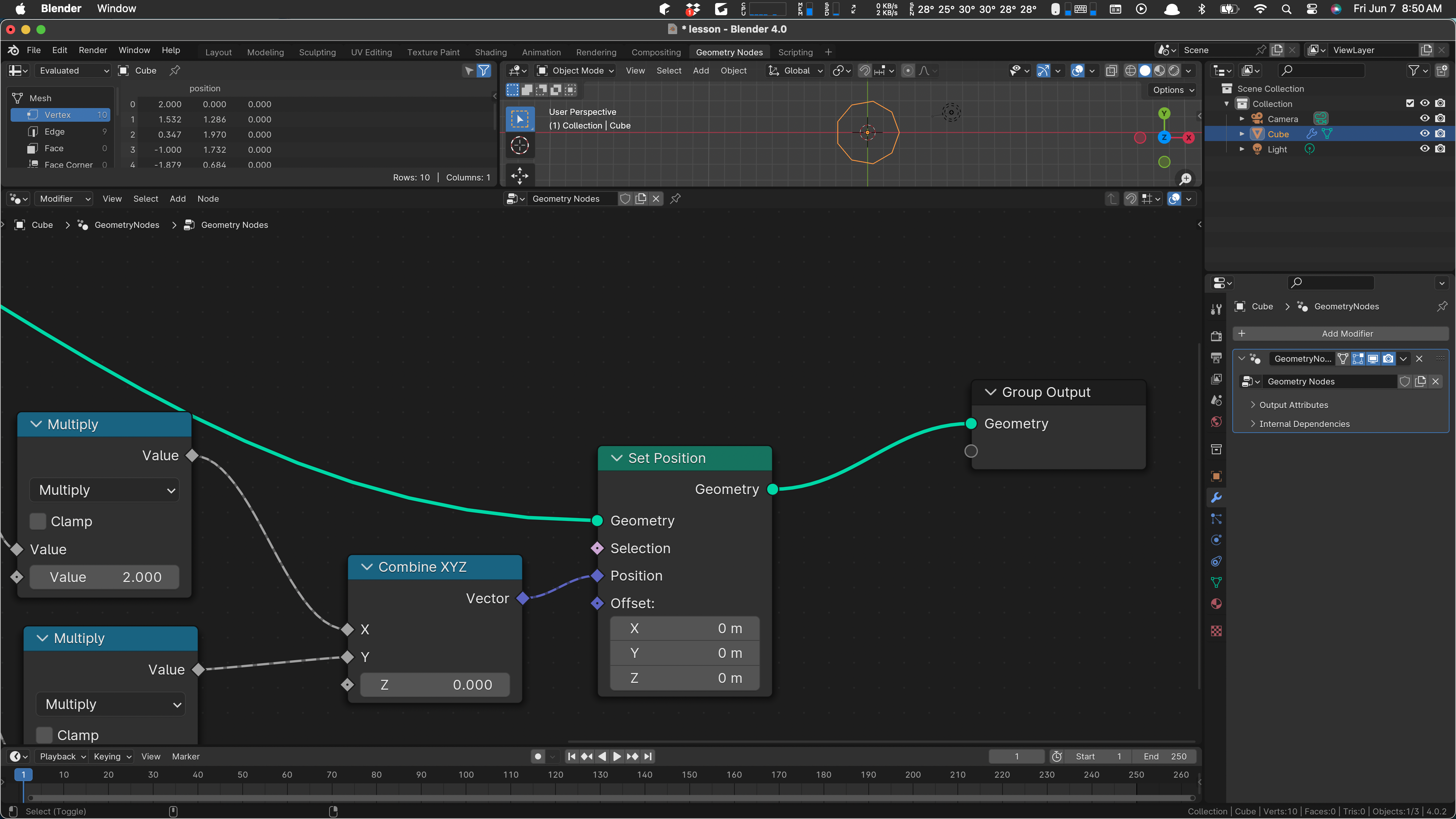
Notice that our circle and its nine segments has appeared in the scene. Set to top-down (mode 7) if you don’t see it.
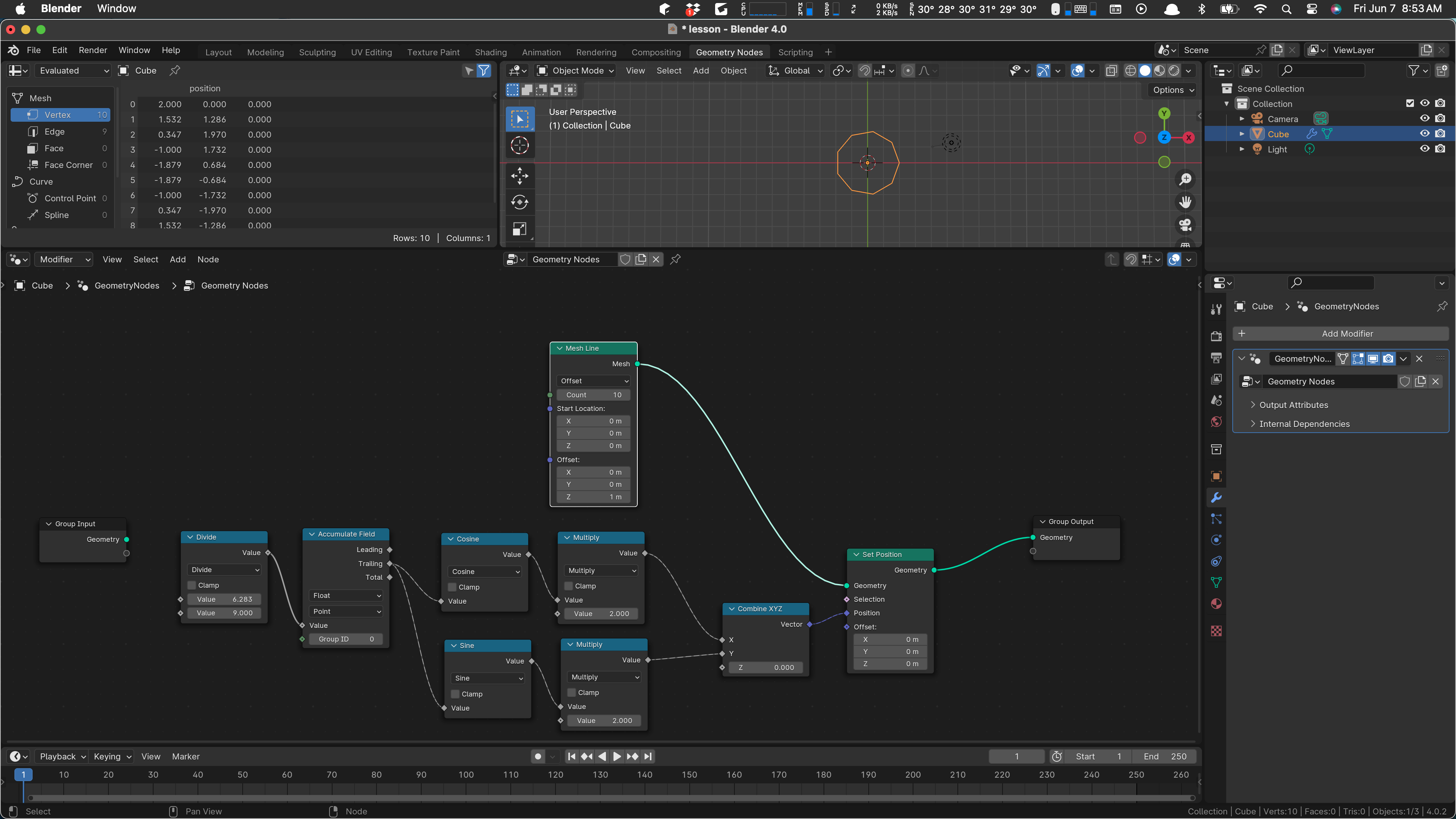
Hurray! We have a working node setup:
We can play with the count, change the radius, and so on. We can even add some of these values as parameters on our node network.
Select the group input, over there by itself. Type an N to get the side panel to open up.
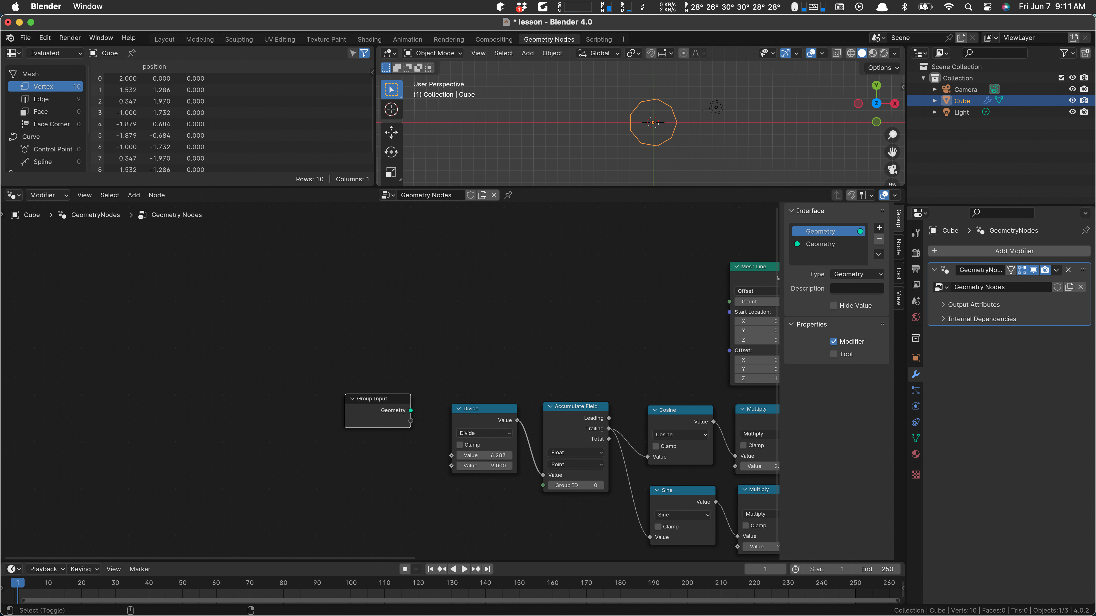
Use the + button to add an input parameter, call it Count. I like to drag it down to leave the Geometry ones at the top.
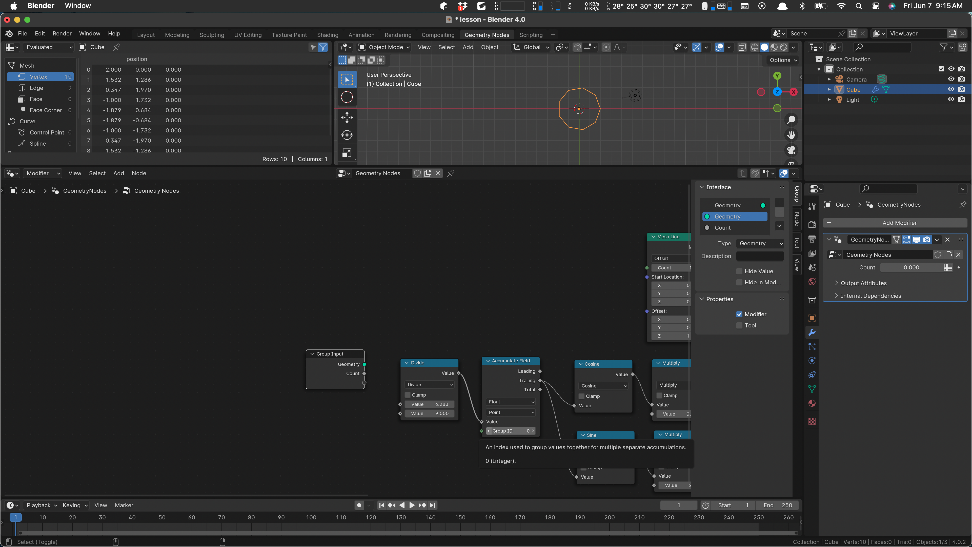
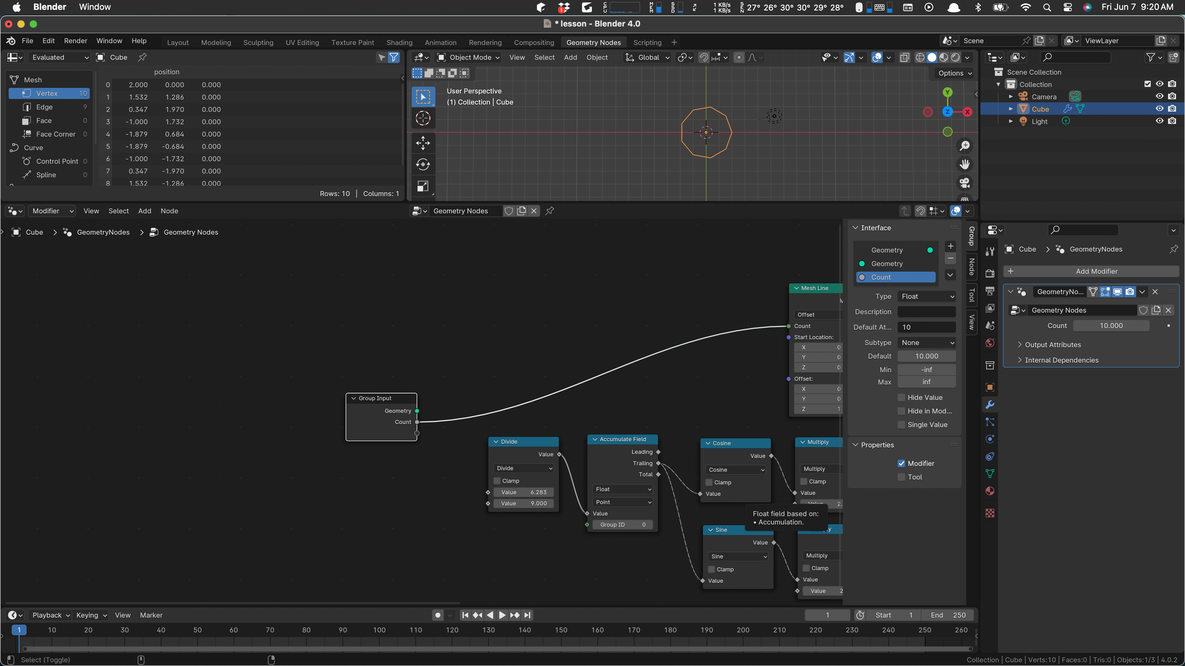
We want to use this value to define how many verts the line has, and we need to use it, minus one), in the calculation of the theta angle step. First wire count to our Mesh Line’s count input. We’ll have to go over to the modifier, where the Count input has appeared magically, and set it to ten there.
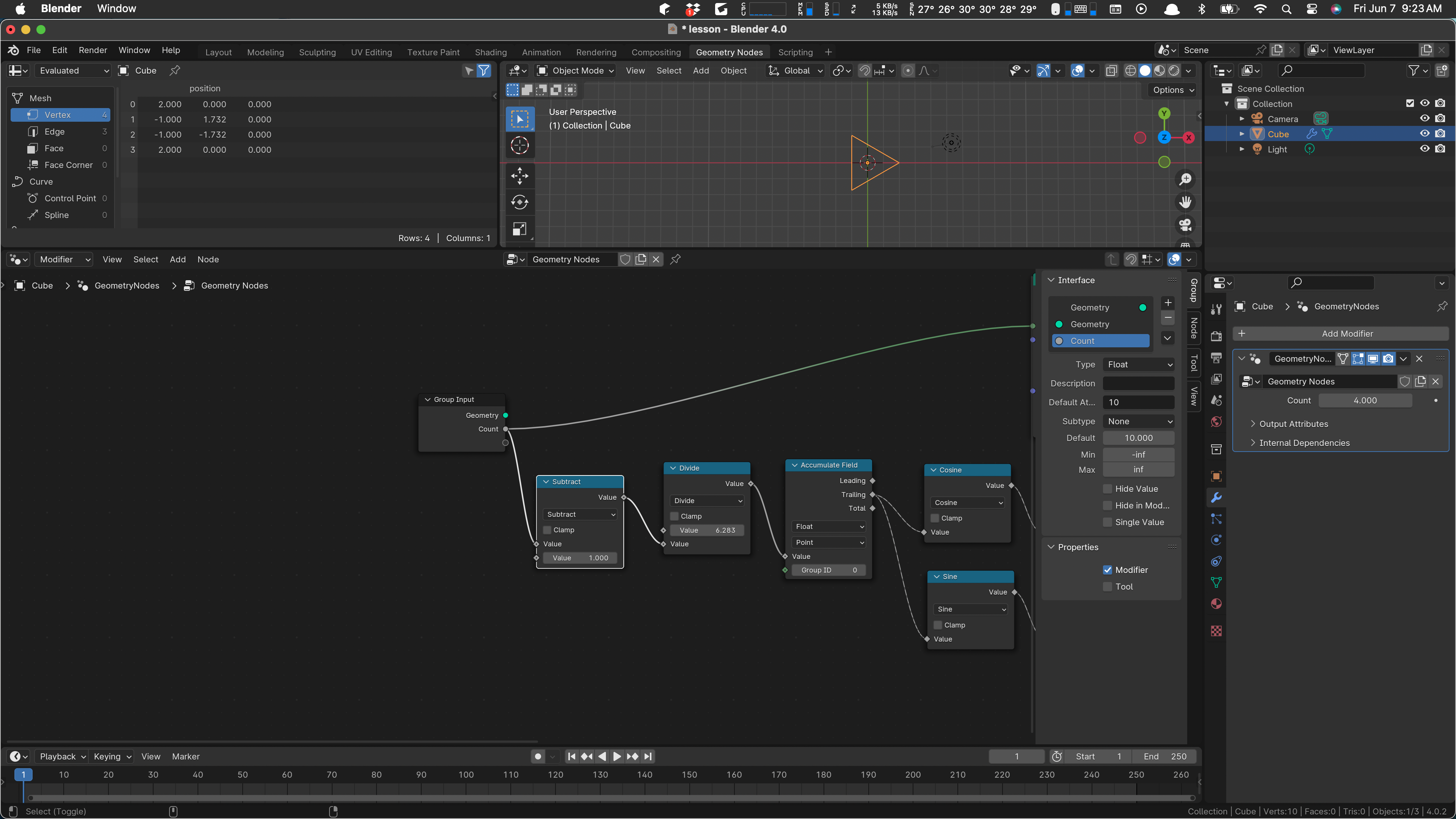
Now let’s make a little space and use count in our initial calculation. Put in a subtract node:
Now if we change the value of count way over in the modifier, the circle gets more or less angular.
We can do the same thing for the radius. That needs to wire into the two multiply operations after sine and cosine:
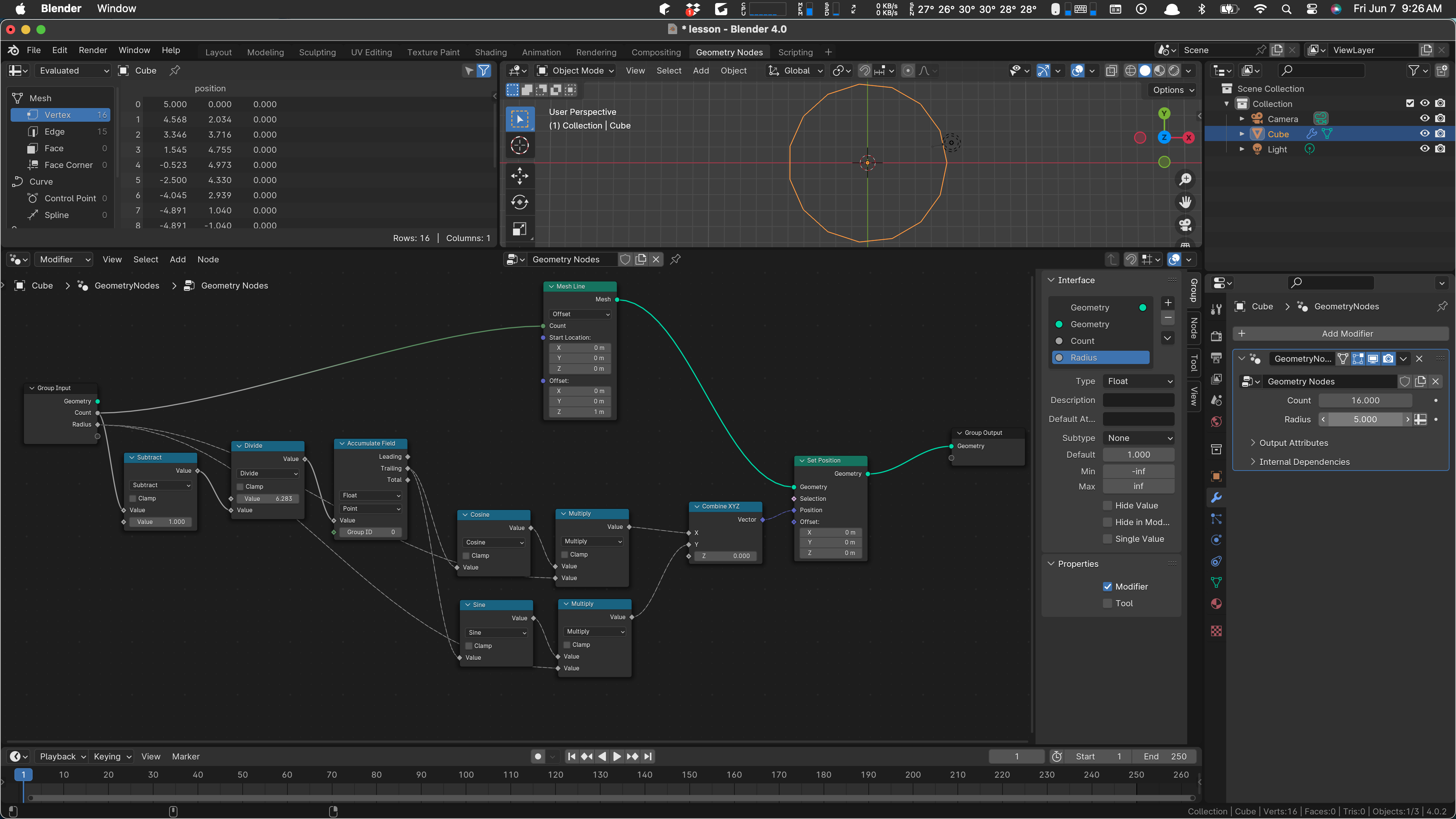
As shown in the picture, we can now set the radius of our circle to any value we want.
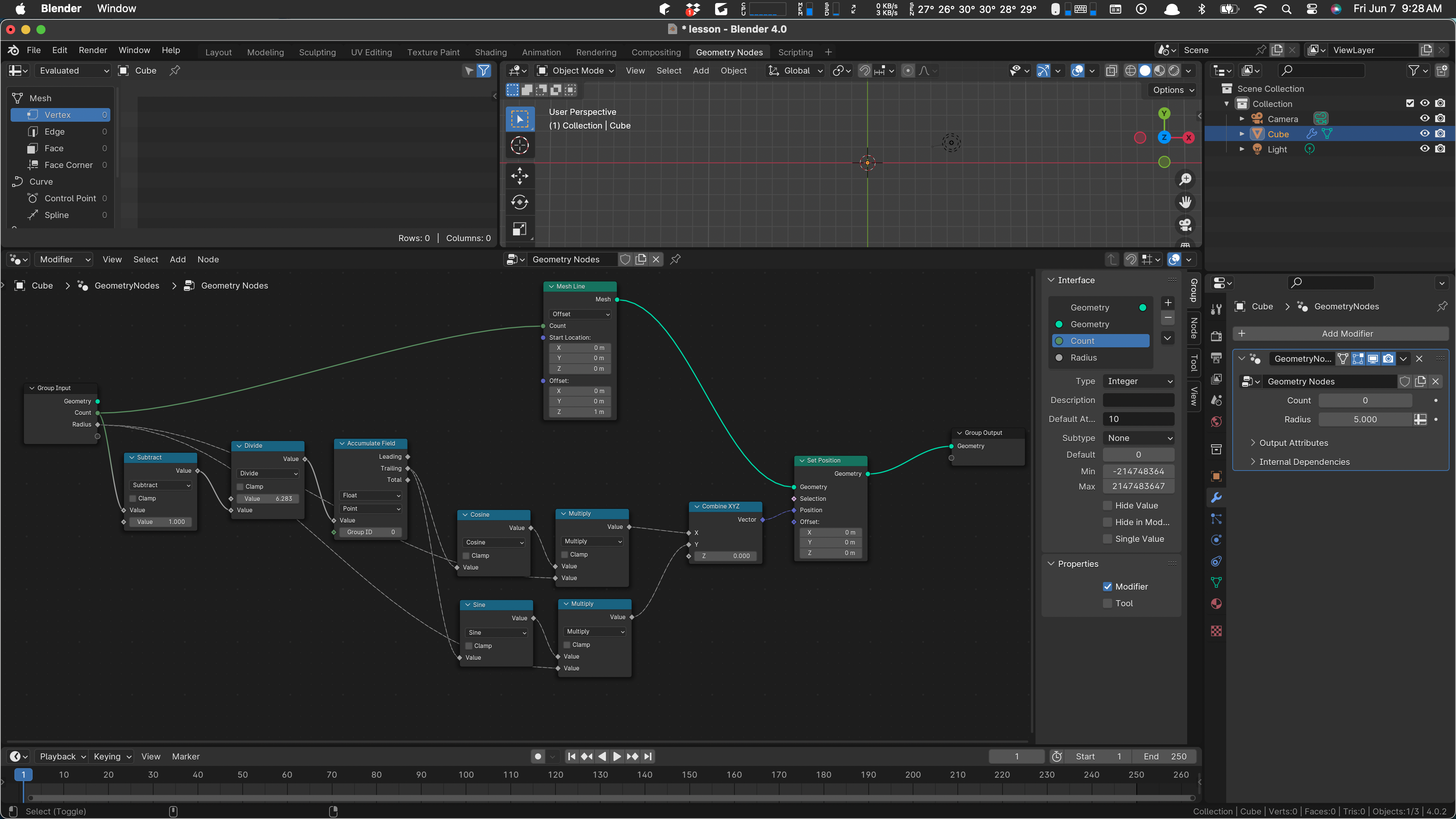
We should change the Count parameter to integer. I think it defaulted to float.
And with that … maybe we can take a break.