Refactoring Geometry Nodes
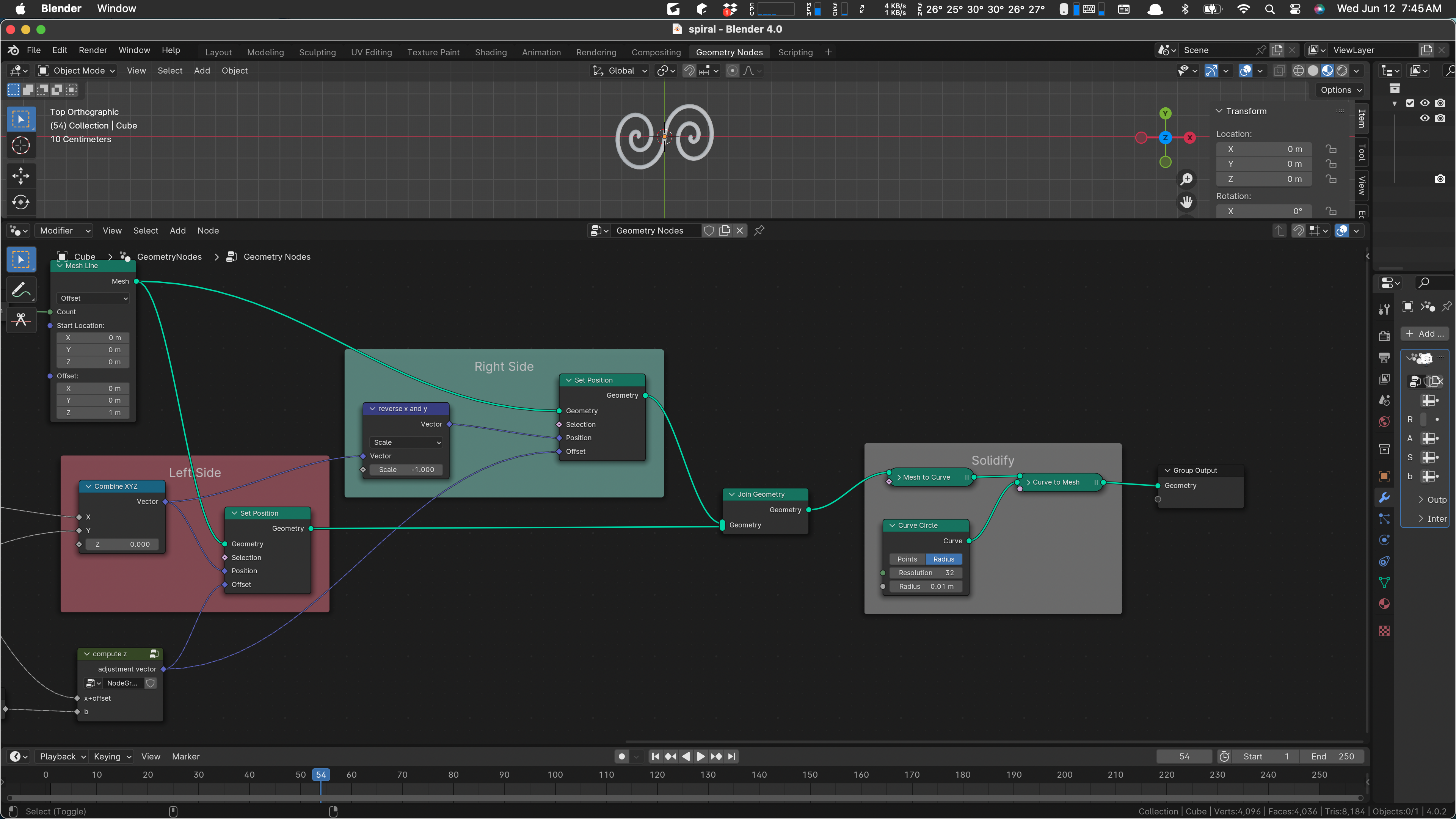
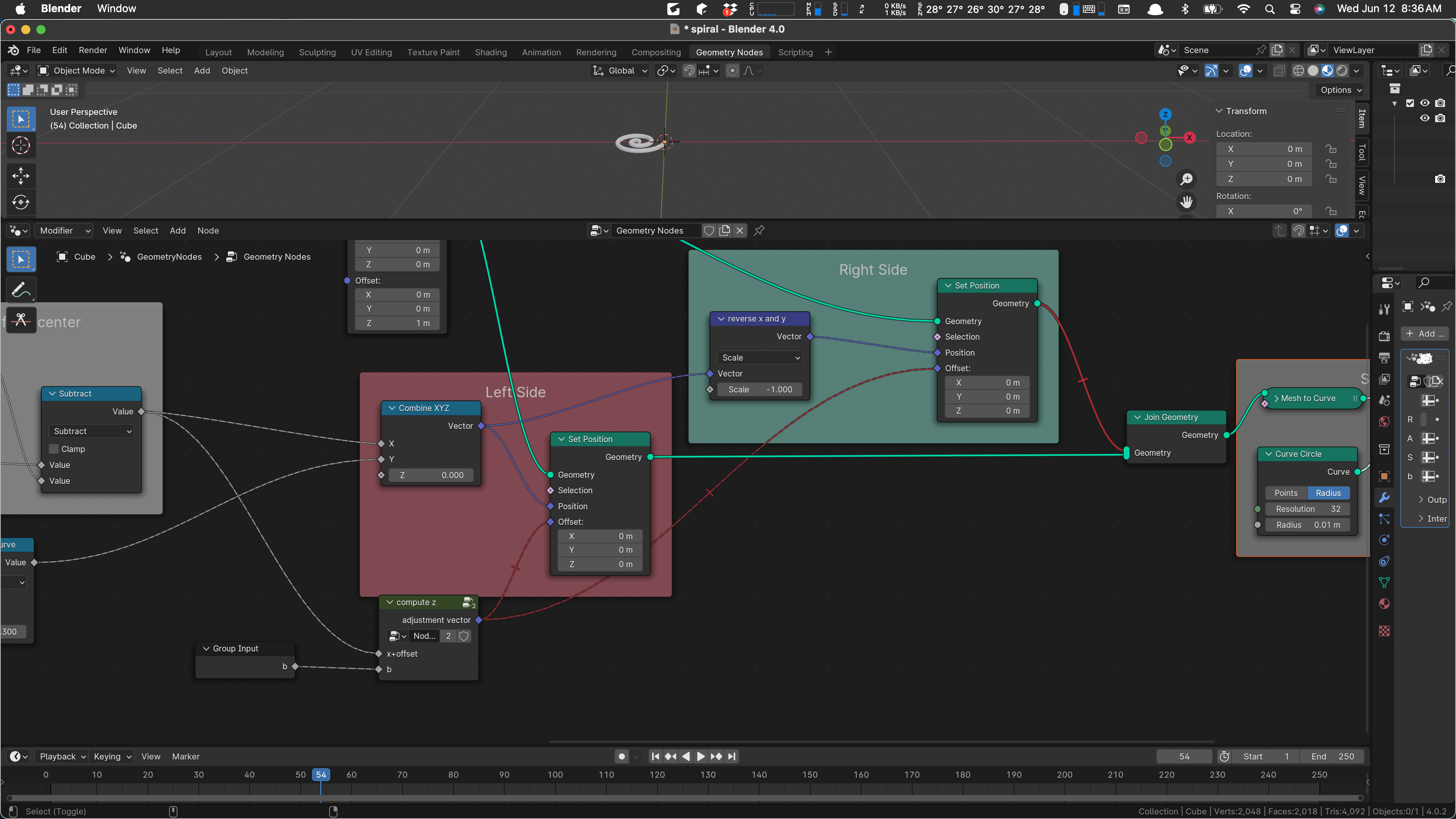
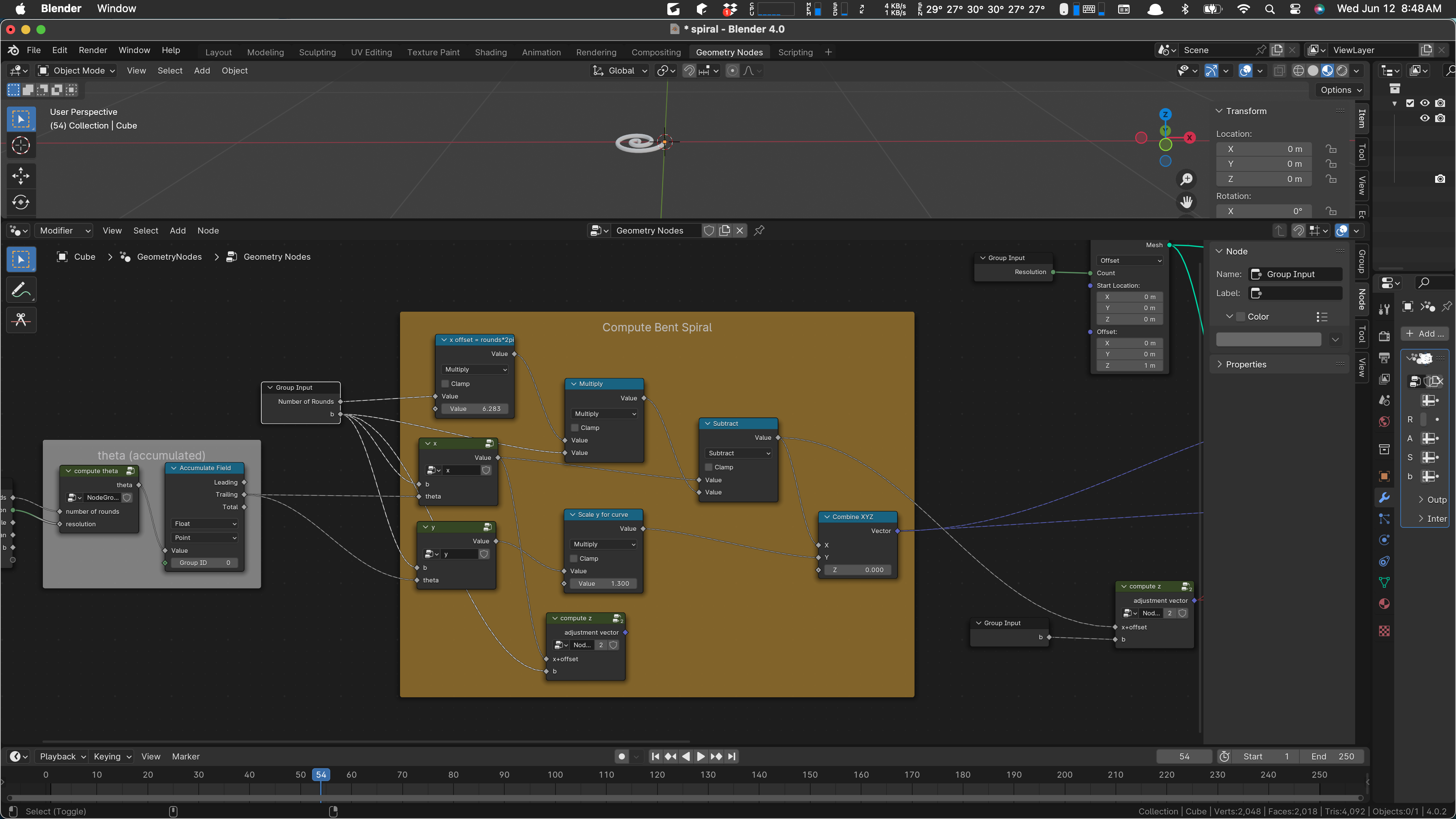
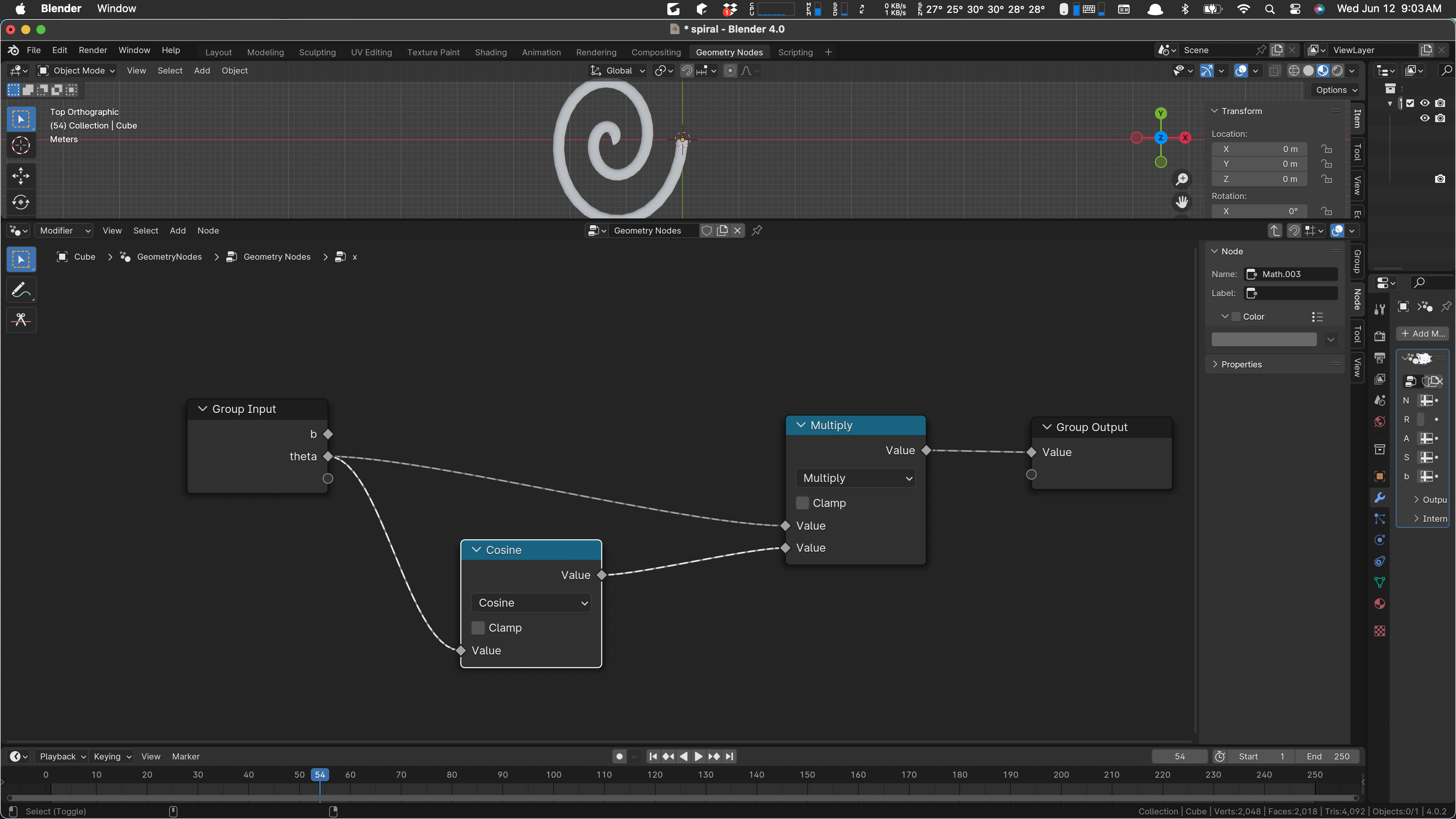
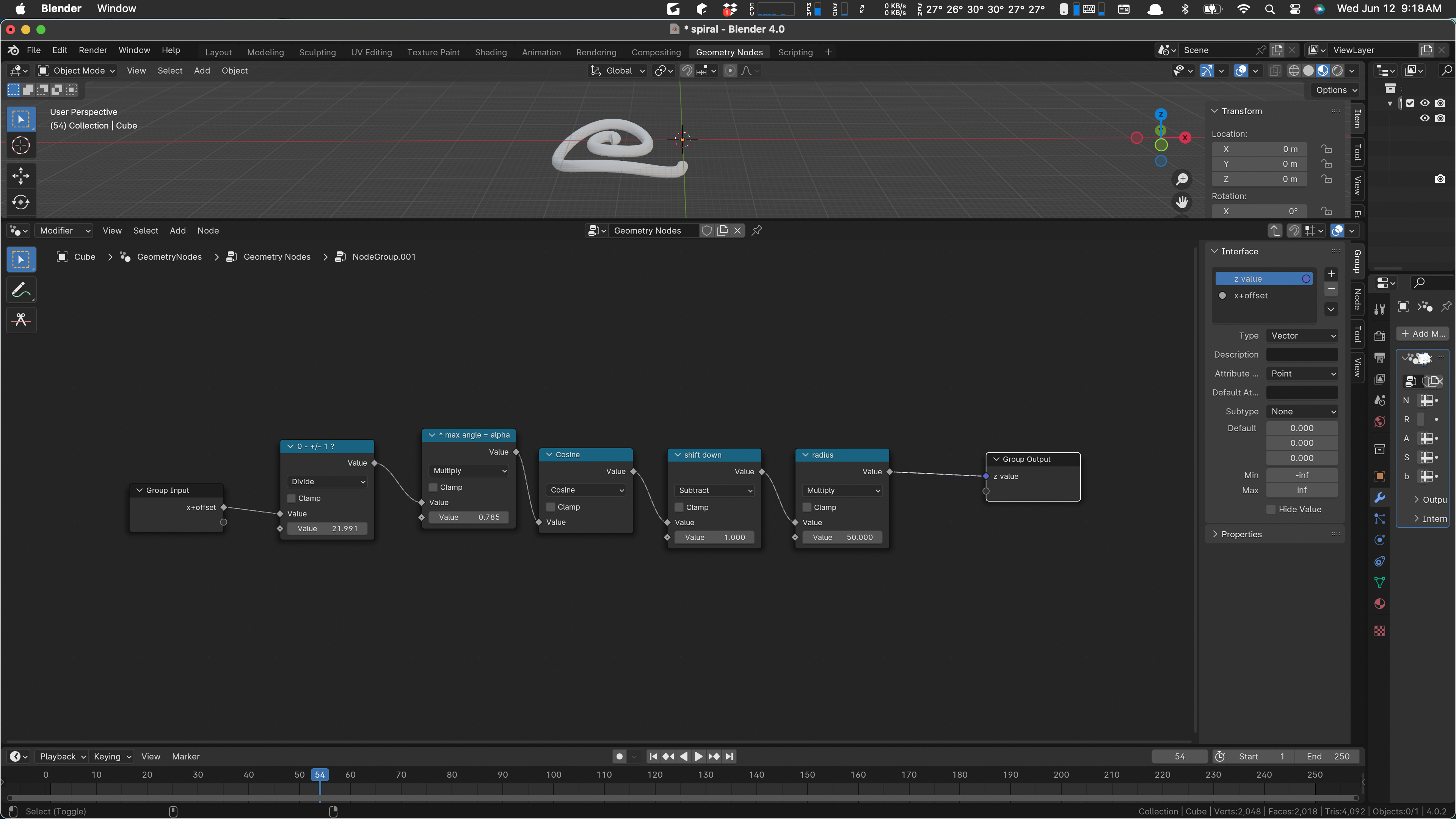
Yesterday, I got the geometry nodes network that produces the bent double spiral working. Today, I’m going to try to improve it. Here’s where we’re starting:
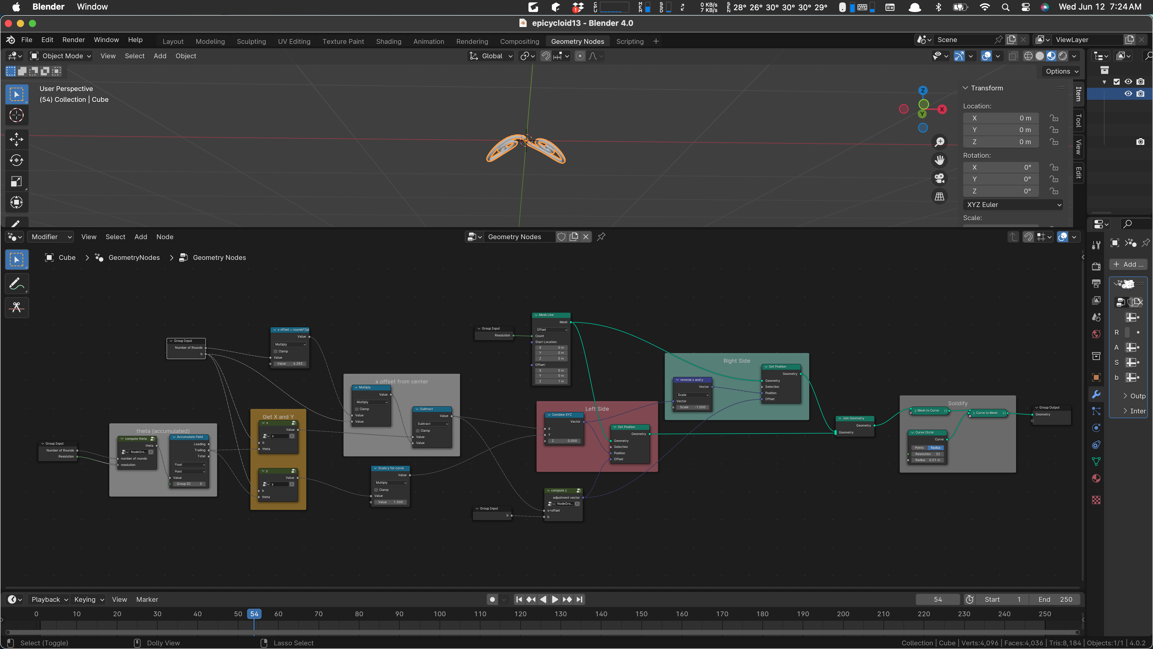
We’ll take a closer look at this as we work. I do have an overall plan. There are currently five apparent parameters to this group, Number of Rounds, Resolution, Angle, Span, and b. (The curious name ‘b’ is called b because that’s the standard variable used in the math definition of the Archimedes spiral, so I used it as is.)
Not all of these parameters are even used. In particular, I think that Span and Angle are not currently used. I think I’ll leave them in, because they actually showed up in the pencil and paper math I did when I was working this out.
The overall purpose of this script is to make a bit of decoration, consisting of a double spiral like this:
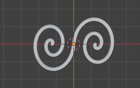
The spiral is to be bent a bit around the y axis in the picture above, to make it wrap around a round object as a sort of decoration or guard.
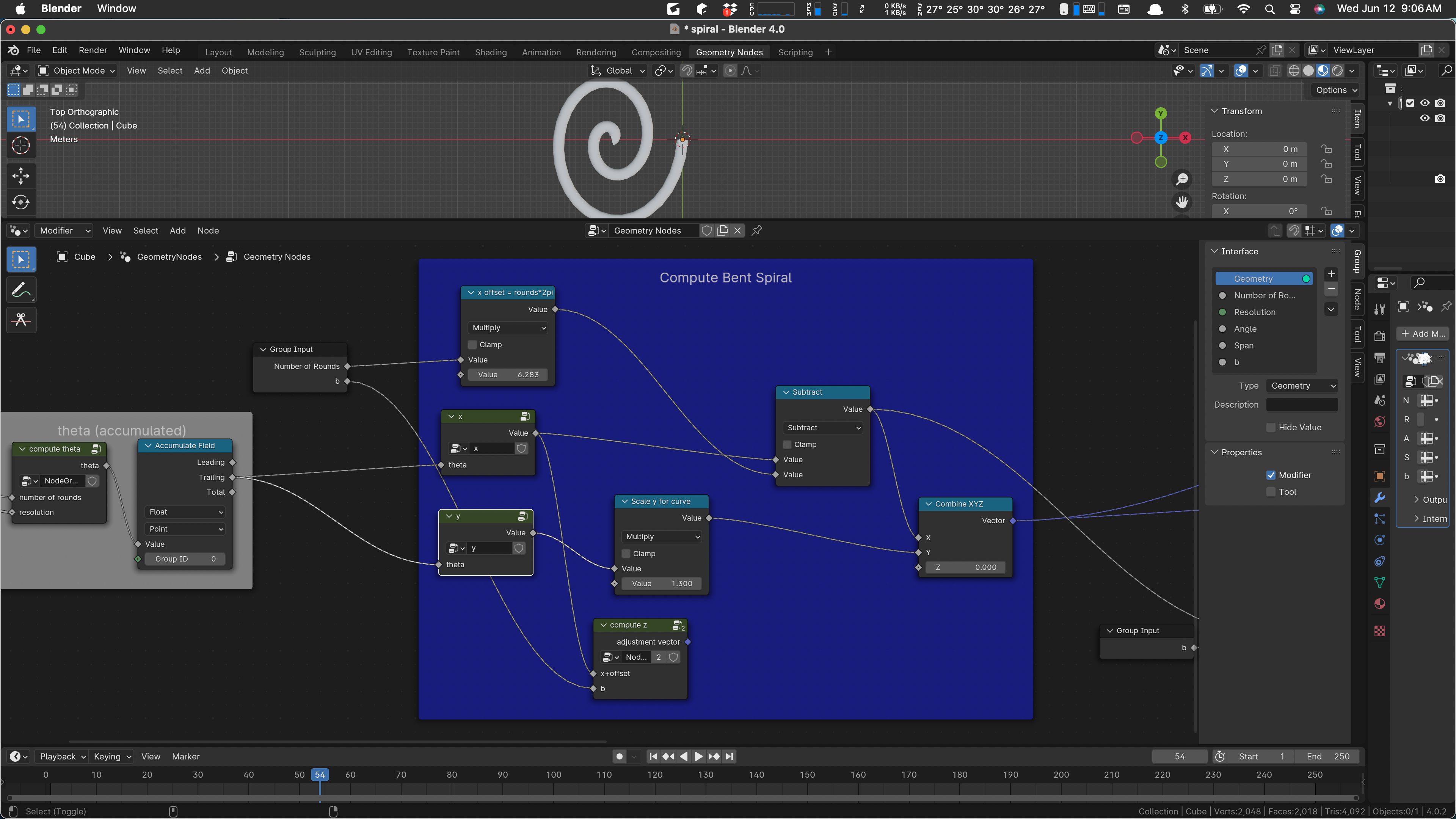
There are four occurrences of the group parameters, one on the left, and one a bit above it:
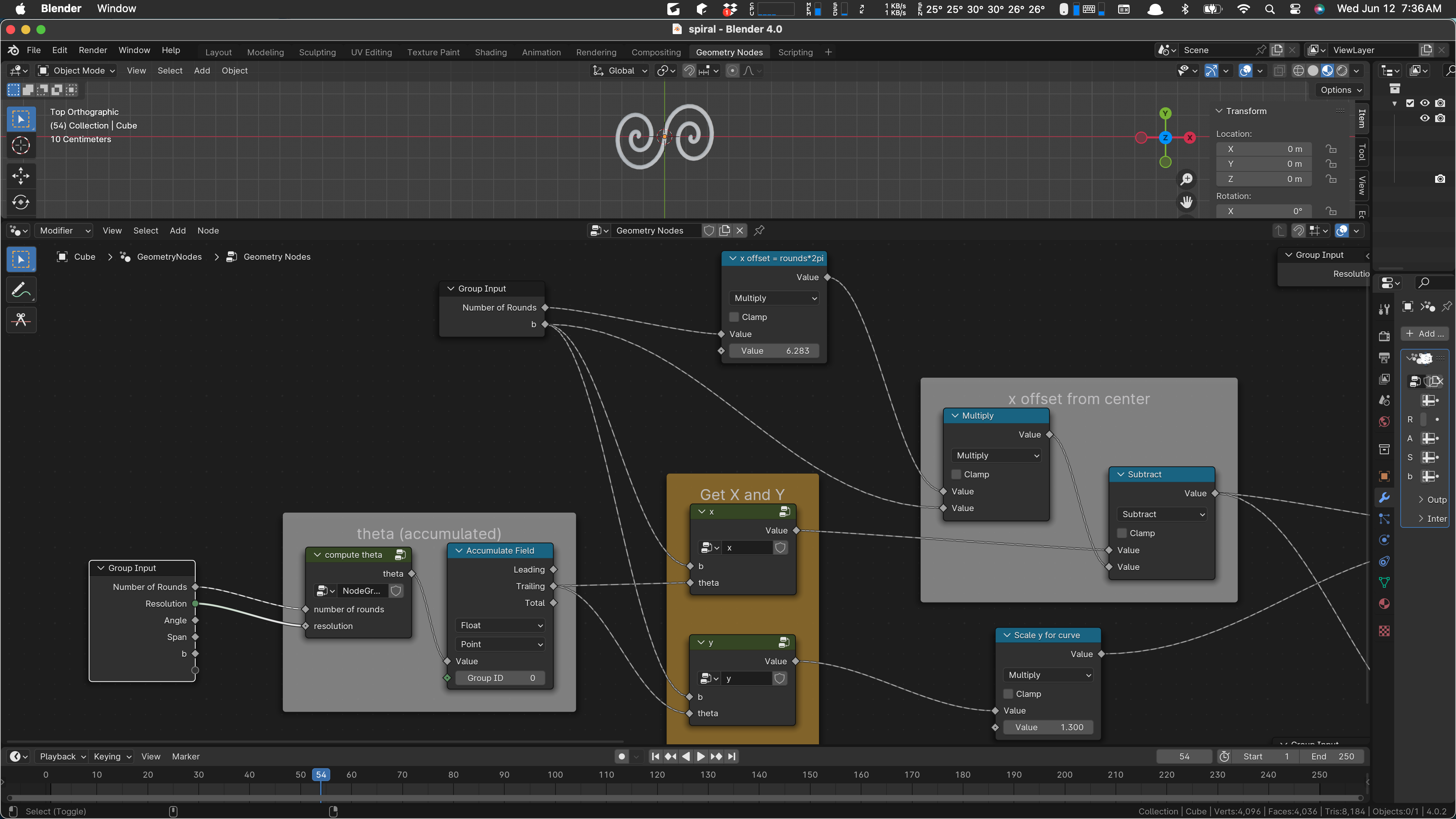
The first one is just setting up our desired iteration. Our input object is a mesh line broken up into “Resolution” segments, and we propose to move its vertices to points on the spiral, “bending” the line into a spiral shape. As always, if you have enough verts and do a little smoothing, it’ll look like a curve.
The second input above is serving two separate ideas. At the top, we are computing the amount to move the spiral on the x axis, so that its outermost point is at the origin. (Spirals start with their innermost point at the origin.) Since a spiral progresses outward at a rate of 2 pi per revolution, we compute that offset here and use it later on.
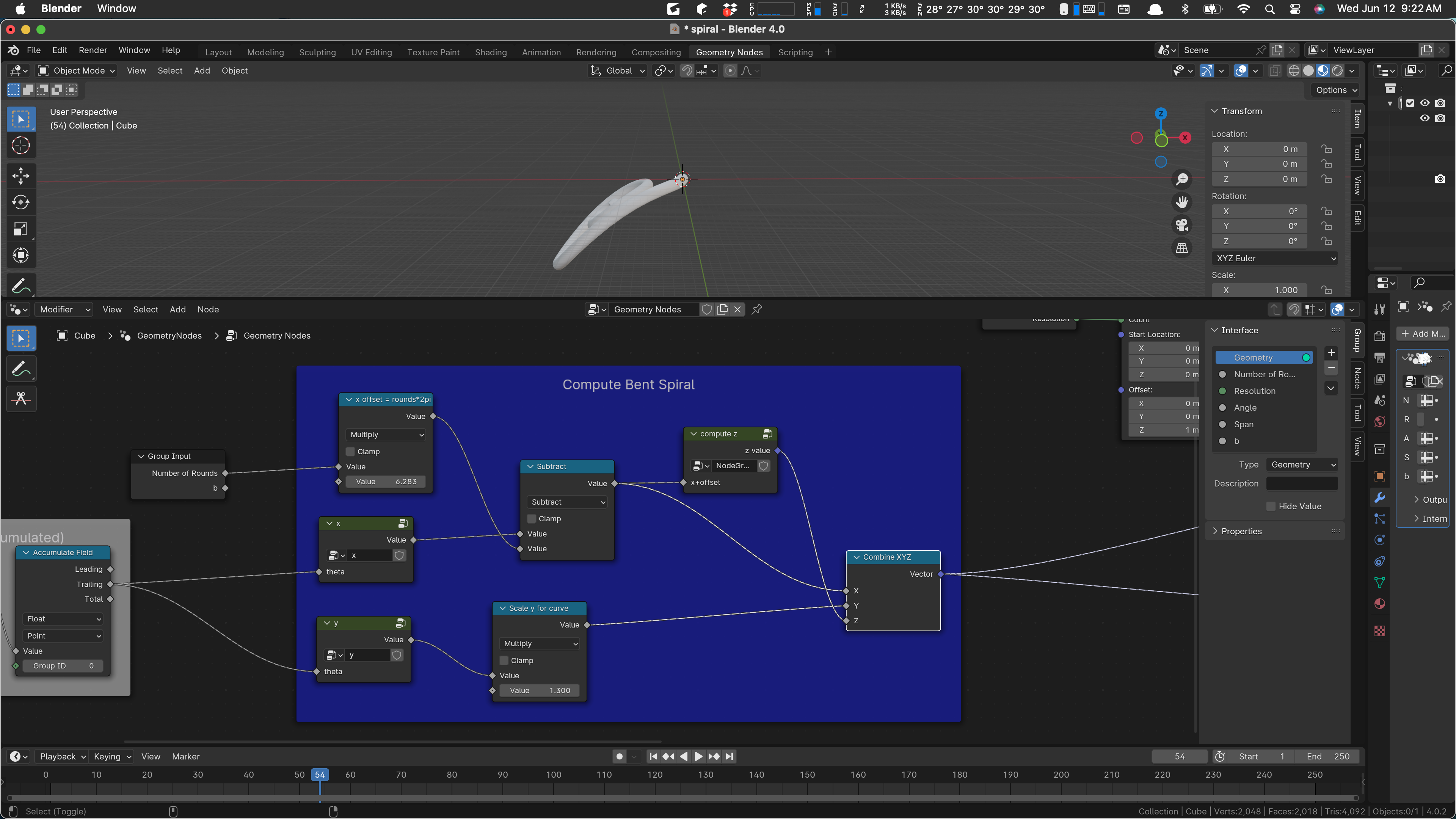
Two more uses of our inputs occur later on:
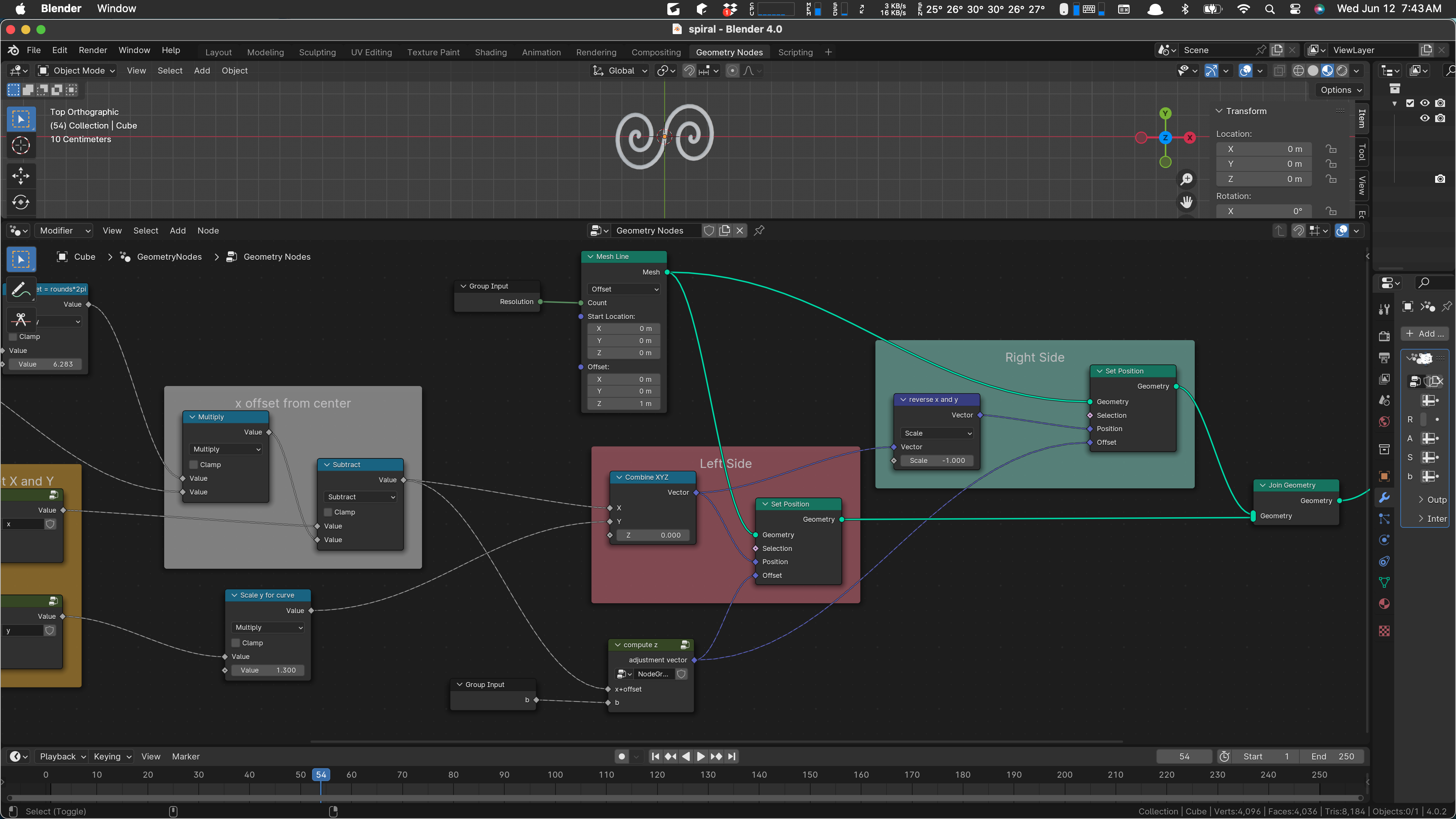
The one at the top produces our mesh line, and the one at the bottom is part of the bending logic. Its use is a bit ad-hoc, but it’s essentially scaling the radius of the bend. The bending calculation is done in the sub-network labeled “compute z”. We’ll probably look at that later on.
As shown above, we compute one side of the spiral, then the other (it’s a duplicate with x and y negated) and produce the output by joining those two geometries and then converting to a curve, adding a profile to the curve to make it a bar or tube, and we’re done.
Let me mention here that there is, in geometry nodes, a Mesh Spiral. I tried to use it to accomplish what we do here but was unable to figure out how to bend it in a simple way, so I returned to this scheme. There may be a better overall algorithm than this one. Maybe I’ll work on that. For now, what we want to do is to simplify this network.
Why? At least two reasons:
- Practice. I’d like to become competent with geometry nodes, as they are kind of the way of the future, and similar nodes are used in shading, and so practice has value in making me a better Blenderator.
- Maintenance. I am not sure that I like the result when it is put in place in the virtual world. So I may wind up wanting to do something similar to this but with a different base shape.
- Futures. (I did say “at least”.) It might be useful to be able to make other scroll-work kinds of objects, and if the components of this network are well-factored, we might be able to reuse bits of them, or at least review them for ideas in new networks.
Maybe those are my reasons. In any case I’ve decided to try to simplify this network.
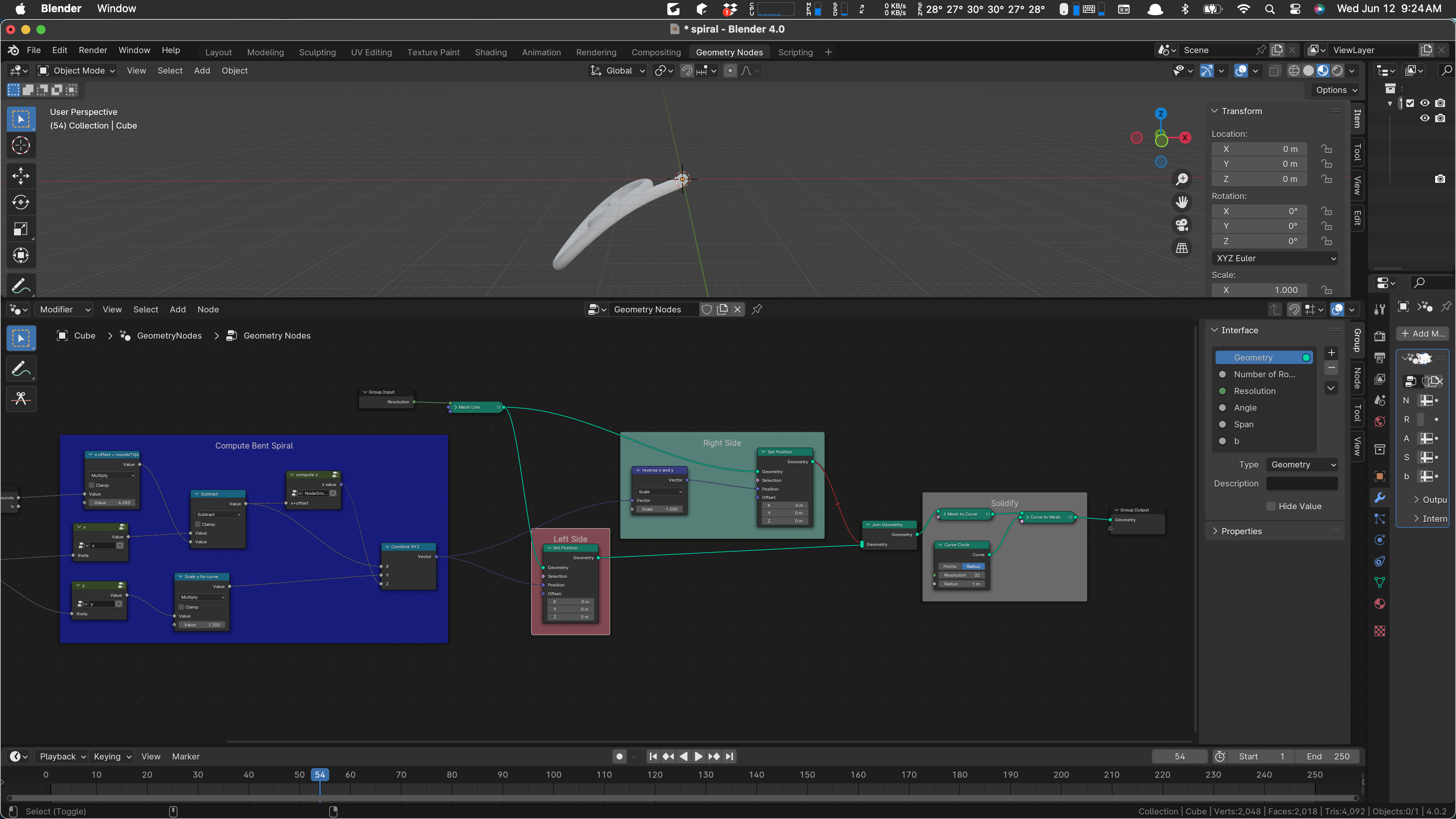
Where shall we start? Let’s start by considering the various sections that seem to me to be modules or separate ideas or something like that. Some of the network already has frames, including:
- theta (accumulated)
- Get X and Y (uses two similar sub-networks ‘x’ and ‘y’)
- x offset from center
- Left Side
- Right Side
- Solidify
There is one other sub-network ‘compute z’, as I mentioned above. It’s the z computation that imposes the bend, by assigning a z value to each point in the spiral, dragging them downward by suitable amounts.
Now the way things are, you’d think that Get X and Y, x offset from center, Left Side, and Right Side could be all one thing, maybe “Make Two Flat Spirals”. (There might be a breakdown inside as well.) But as things stand, the z logic is kind of patched into the middle of the spiral creation.
If bending is part of the idea, then it seems to me that we should have a Get Z that is co-equal with getting X and Y.
I think I’d like to make the following changes, roughly, to consolidate all the geometry creation:
- Add a Get Z to Get X and Y. It can return zero at first.
- Modify the Get Z to do the bending.
- Remove the bending from where it is now.
I am inclined to remove the b factor, which scales the overall “radius” of the spiral, create a standard-sized object, and scale it later as needed. (It is notable that the standard size of this object with the current Blender settings is about 22 meters wide. This is larger than we are likely to need.)
The current Z computation, whatever it does, only refers to ‘b’, as do the X and Y calculations so maybe we can just plunk it inside almost without trouble. (Since we negate the coordinates in the Right Side, we’ll have some work to do there, I suspect. Should be easy.)
How do we add an operation to a frame? I guess we can just drop them in. I’ll duplicate the compute-z and drop it in.
After I pop it in there I notice that it needs an x-offset value but we’ll deal with that in a moment. Let’s wire up the b and see what we can do inside. I probably should have looked inside before. It goes like this:
Right, that may have been a bad first move. Z takes the X value as part of its input, and it also needs that value offset … the shift that moves our center to the end of the spiral. Let’s feed our function the x value (without offset) for now:
If the output of this were correct, we could just plug it into a combine. But the output of our function is currently a vector, not a Z value. I’m starting to think that we weren’t ready for this change.
As things stand, we are passing the separate X, Y, and Z values around, adding a value to this one, scaling that one and so on.
I don’t think I’m good enough at this to do what I’d do in code, which would (a) probably never have gotten quite this awful, and (b) be something I know how to refactor in small steps. Here, I think I need to break it and then fix it.
Let’s mute out the second side.
Now we’ll mute the existing bend, which will make the thing flat.
Now what I think we would like to do is to have our Get X Y and Z box produce geometry, not individual X Y and Z. We can work up to that by finding out Combine XYZ and moving it left.
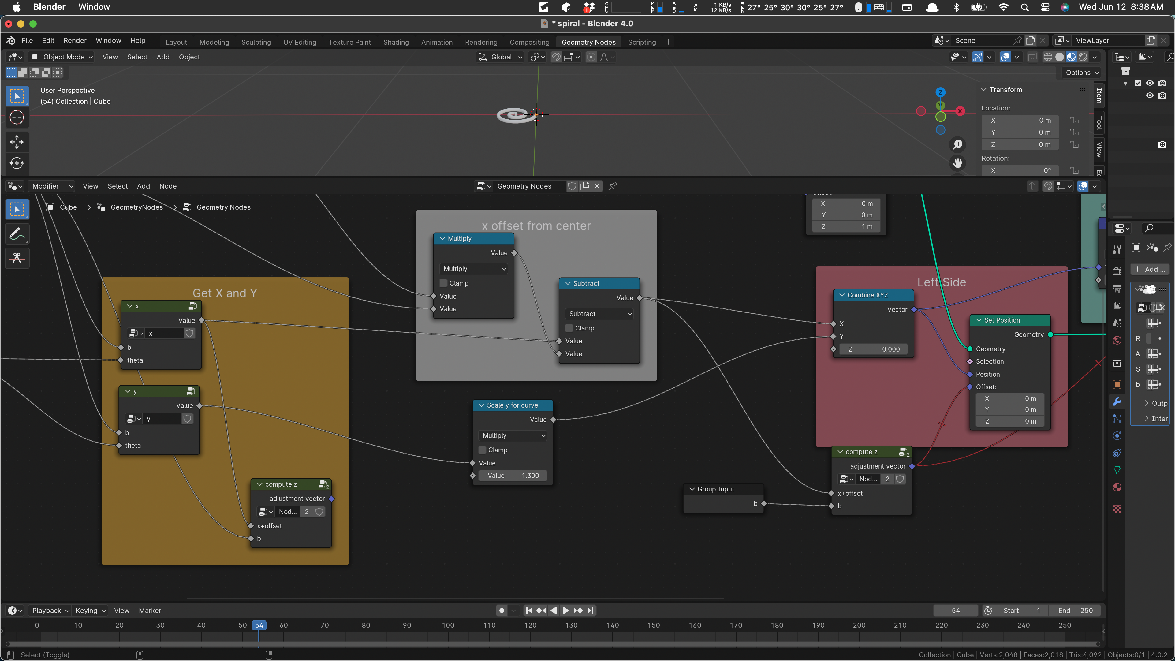
As I look at that it seems that I can just drag the “scale y for curve” inside the frame.
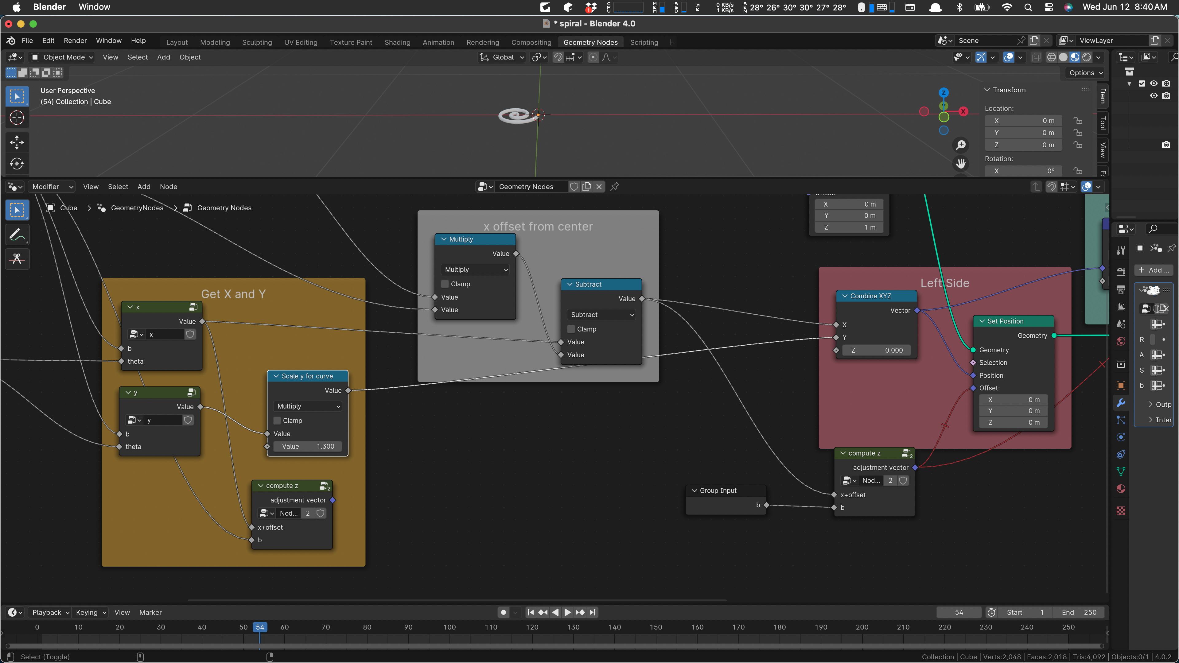
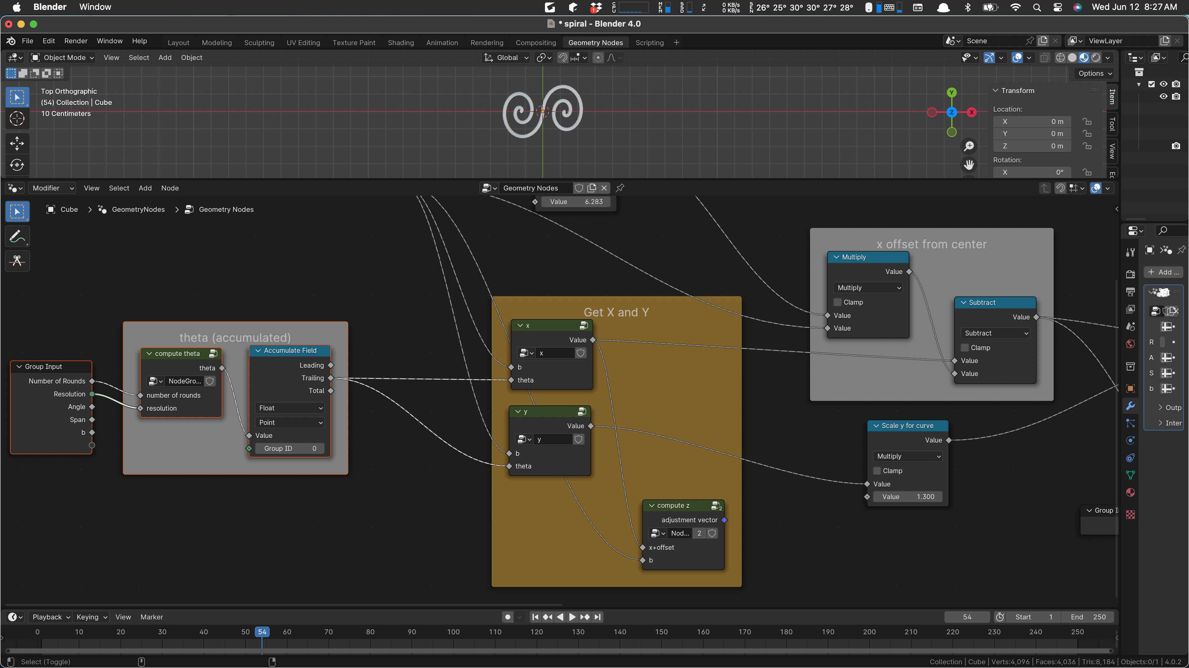
Yes. And let’s drag in the offset adjustment as well, which would let us move the combine in. I think that leads to a good place.
Yes, and now we see that we want to move that x offset node in as well, and the combine … and then we have everything caged and can see about improving it.
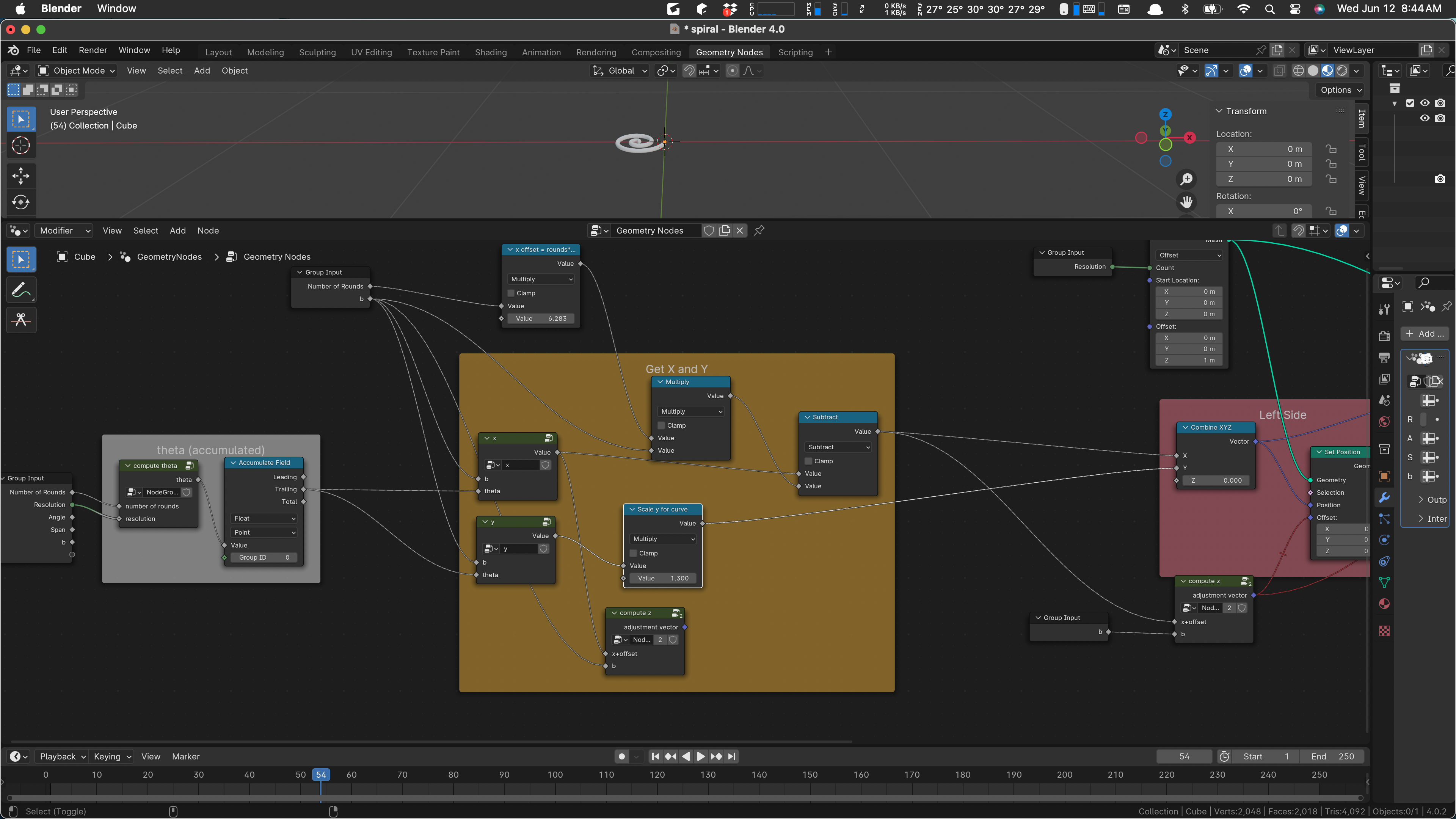
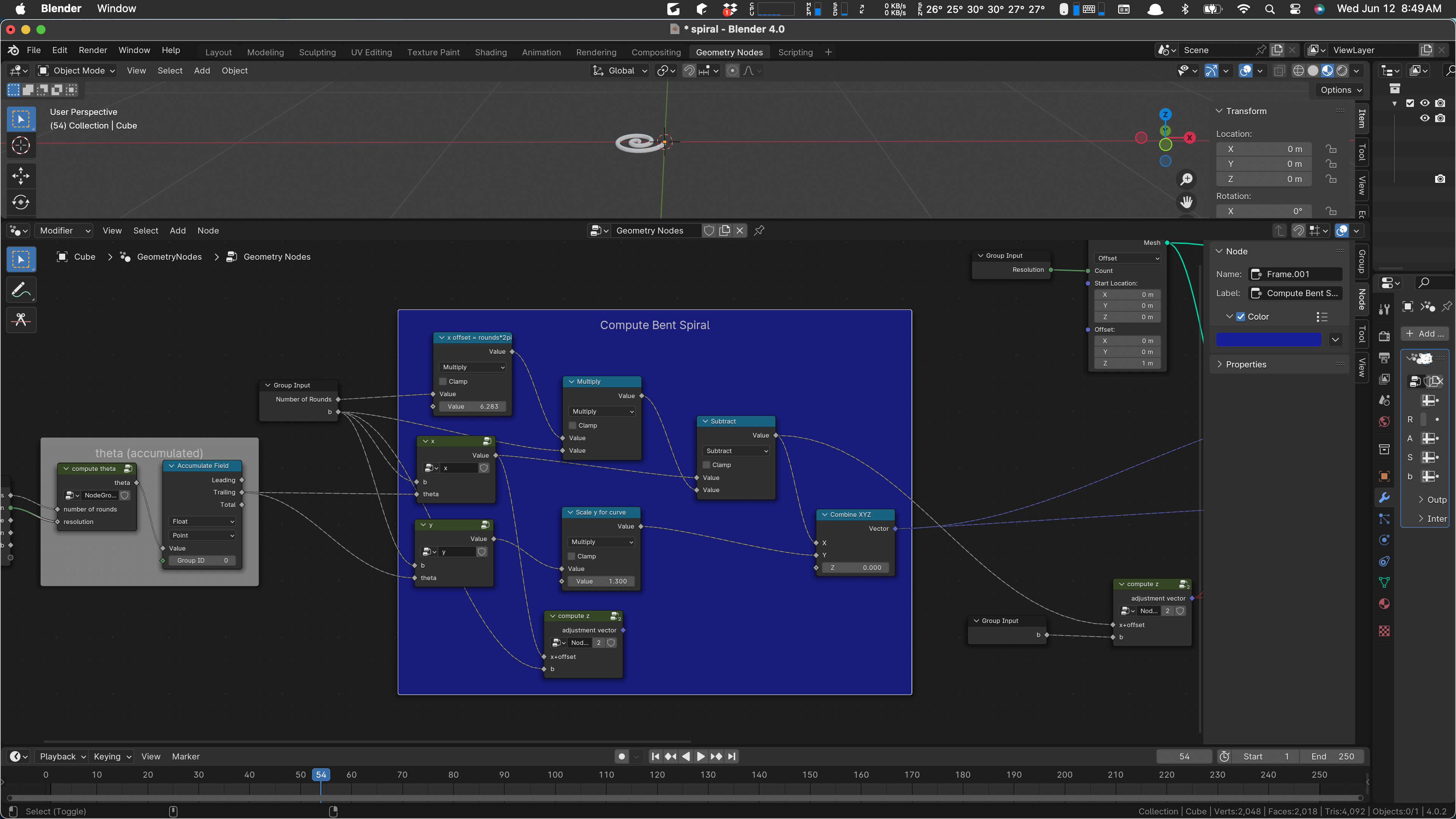
I’m finding that color hard to read, so we’ll recolor the box.
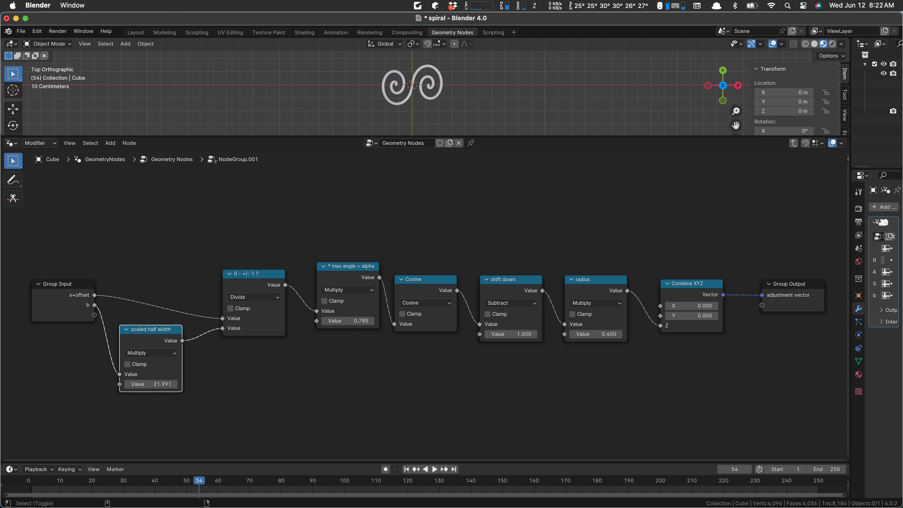
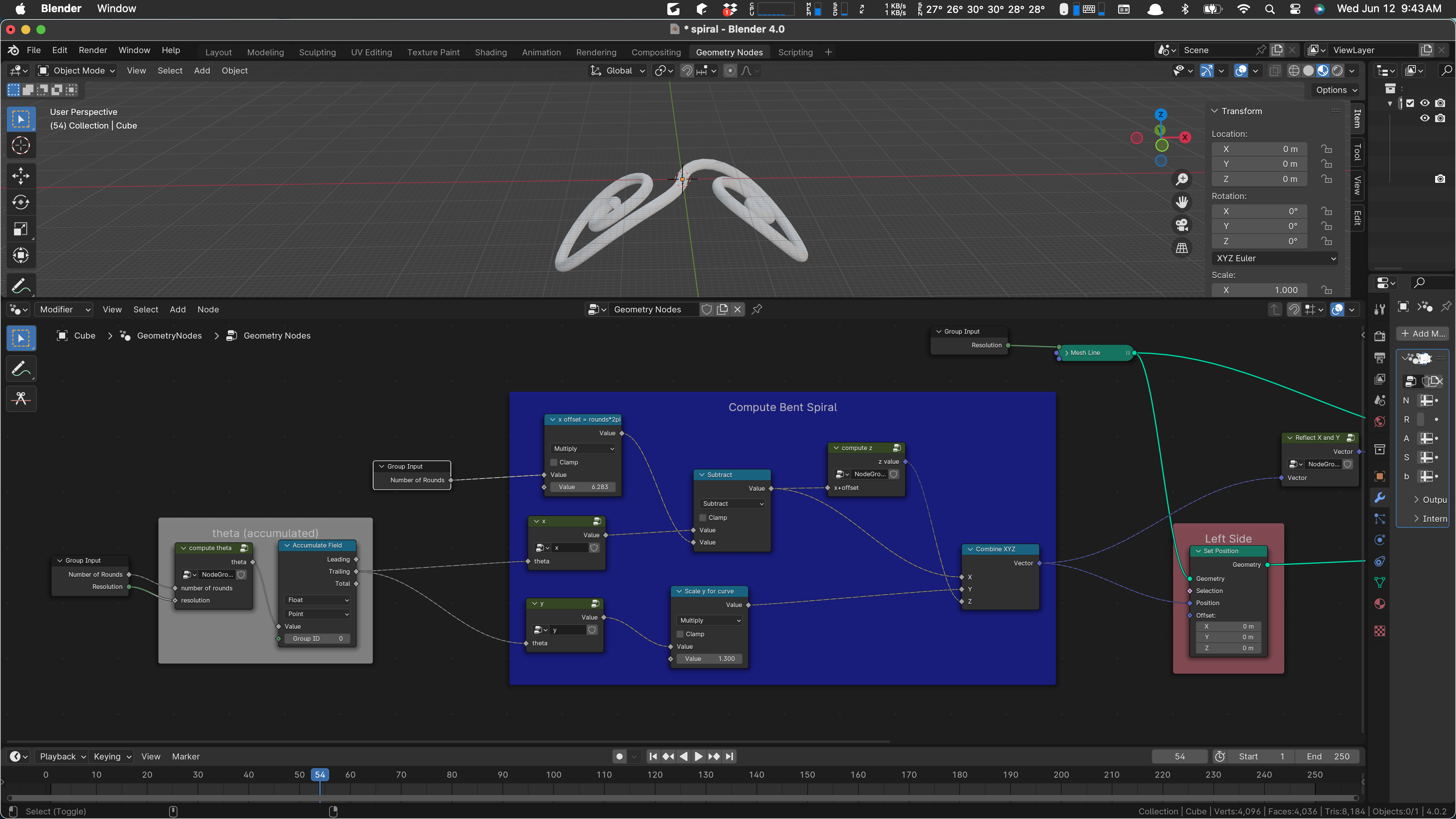
Let’s have a glance at the X and Y calculations before we start moving and changing, just to be sure we know what they are.
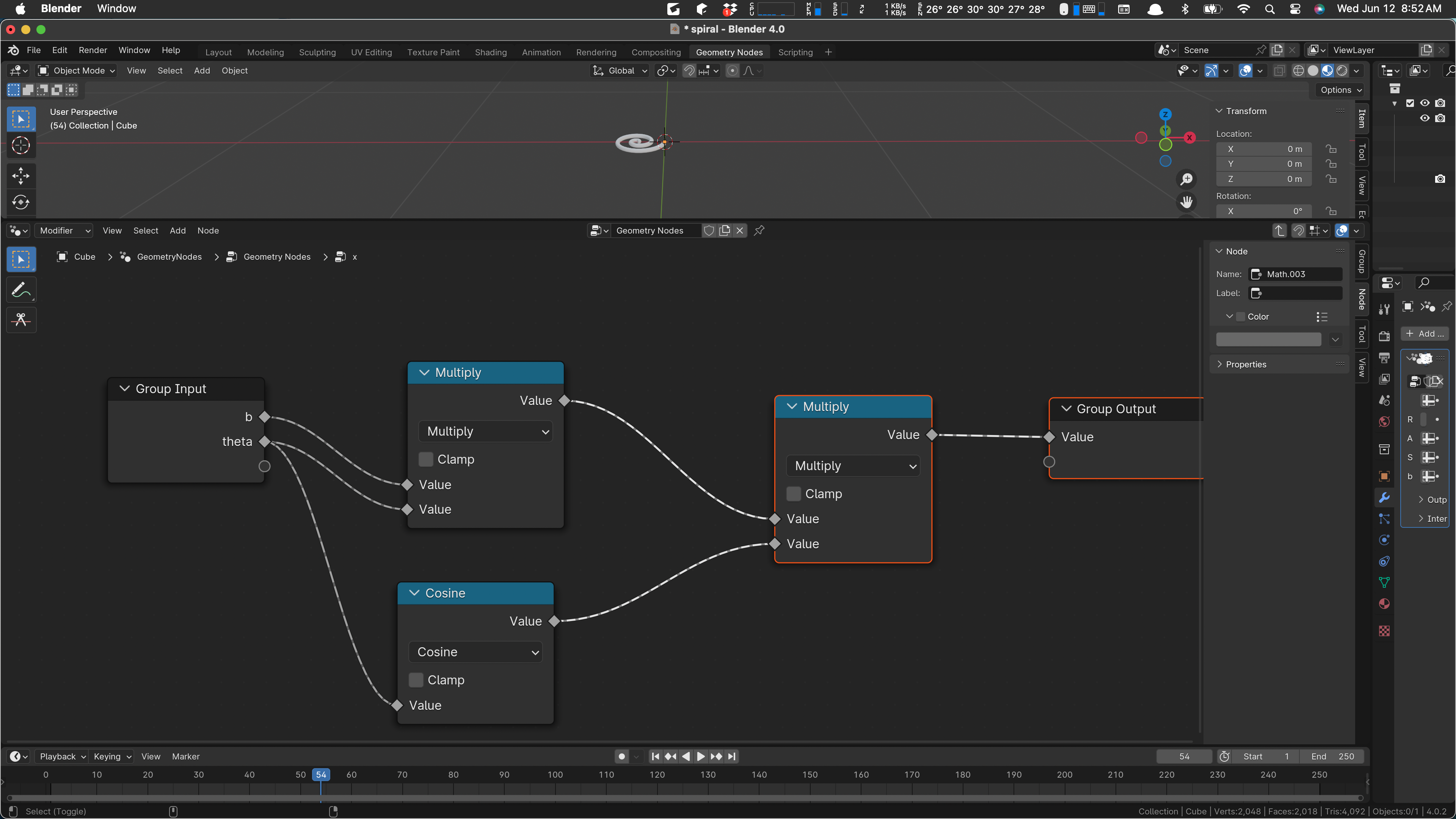
That computes x = b*theta*cos(theta). The y is the same except it uses sin(theta).
The ‘b’ value controls how close together the spiral arms are, the basic span of the spiral. I am inclined to pull that out and scale things later. It would simplify the Compute Bent Spiral a lot. We’ll set ‘b’ to 1 in preparation for that. To make that visible, I need to tweak the size of the profile. We’ll look at that later.
That’s our situation with b = 1. So let’s just unhook it and set all the values in our box to 1.
If b is 1, the multiply at the top of the box has no effect. Dissolve it.
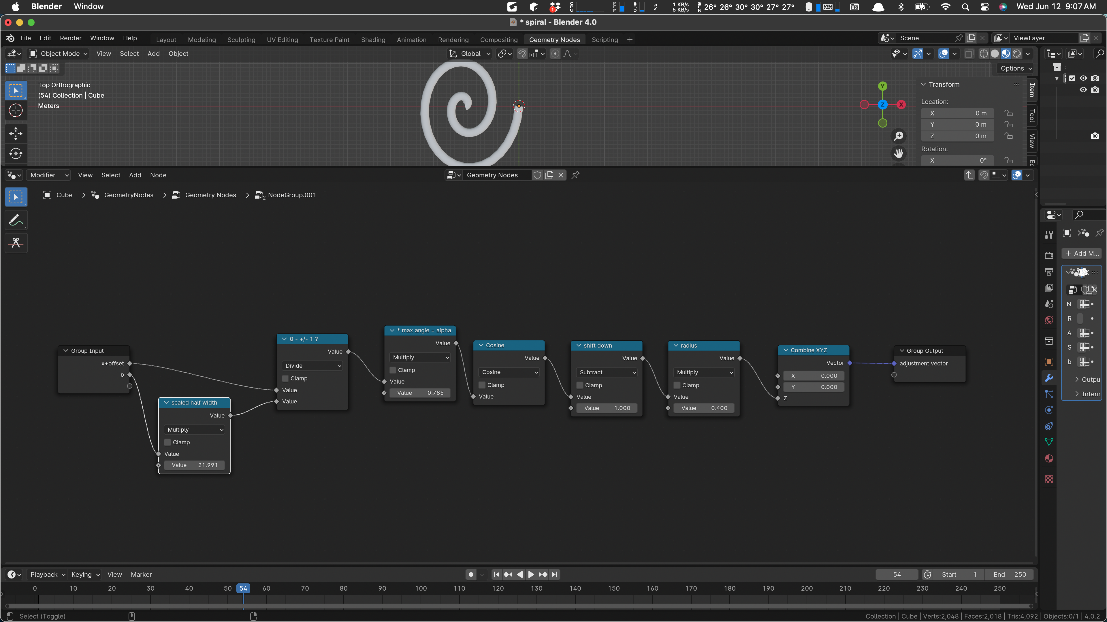
Let’s change the x and y calculations not to use ‘b’:
We just do theta * cos(theta) now. So we can remove the ‘b’ parameter. We do the same with the y. Outside that gives us this:
We can un-wire b from the z calc:
That weird 21 thing is 7 times pi (remember that pi is almost equal to 22 sevenths?) so we can plug that in directly.
We’re going to need to deal with the offset shortly. For now, let’s plug in our Z to the output and see what we get. I expect to get a different curvature, kind of backward.
I change the z function to just return z. I think that’s a small mistake but it may never be detected. Wire it up.

I am surprised. I expected the spiral to be somewhat bent but it is not: it’s clearly flat.
I’ve not been making save points, but I have plenty of undo and I can always erase this article.
I wonder if the z value is just too small to be noticed. Yes!

With the radius set to 50 there, we see that we do get a curvature. It starts in the middle of the spiral, because we do not have an offset. We can give our z calculation the offset x value by rewiring:
And our spiral is bent the way we want it. There are some values that we may want to tweak to get just the shape we need, but for now it’s good.
Now we’re “just” missing the other side.
That side is just muted (the red connection) so I can un-mute it and see what’s what. I expect it to come out in the right place but curving upward.
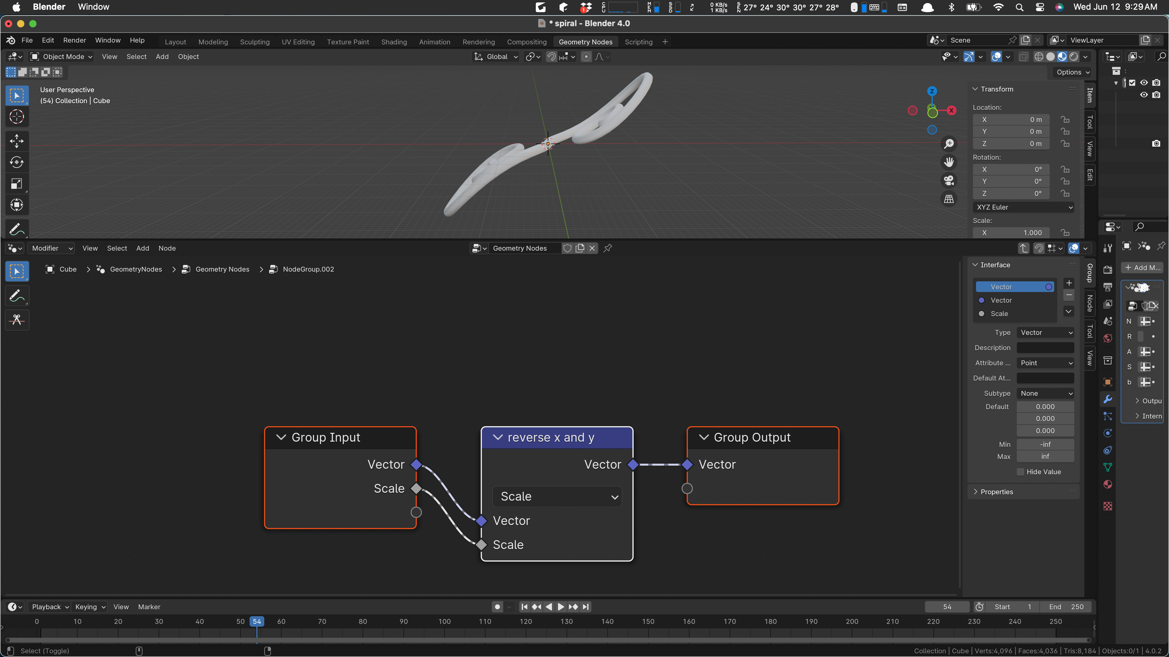
And it does! I love it when a plan comes together. Notice the “reverse x and y” node in the Right Side. It’s multiplying the vector input by -1, which is reversing z as well. We need to do it element-wise. I wonder if there is a good way to do that. I don’t know one offhand, so I’ll make a little function to do it.
We make it a “group”:
We’ll not need the scale input and will get rid of it as we work. Oh … could we just scale this vector by -1, -1, 1? That might be good. Let’s try it.
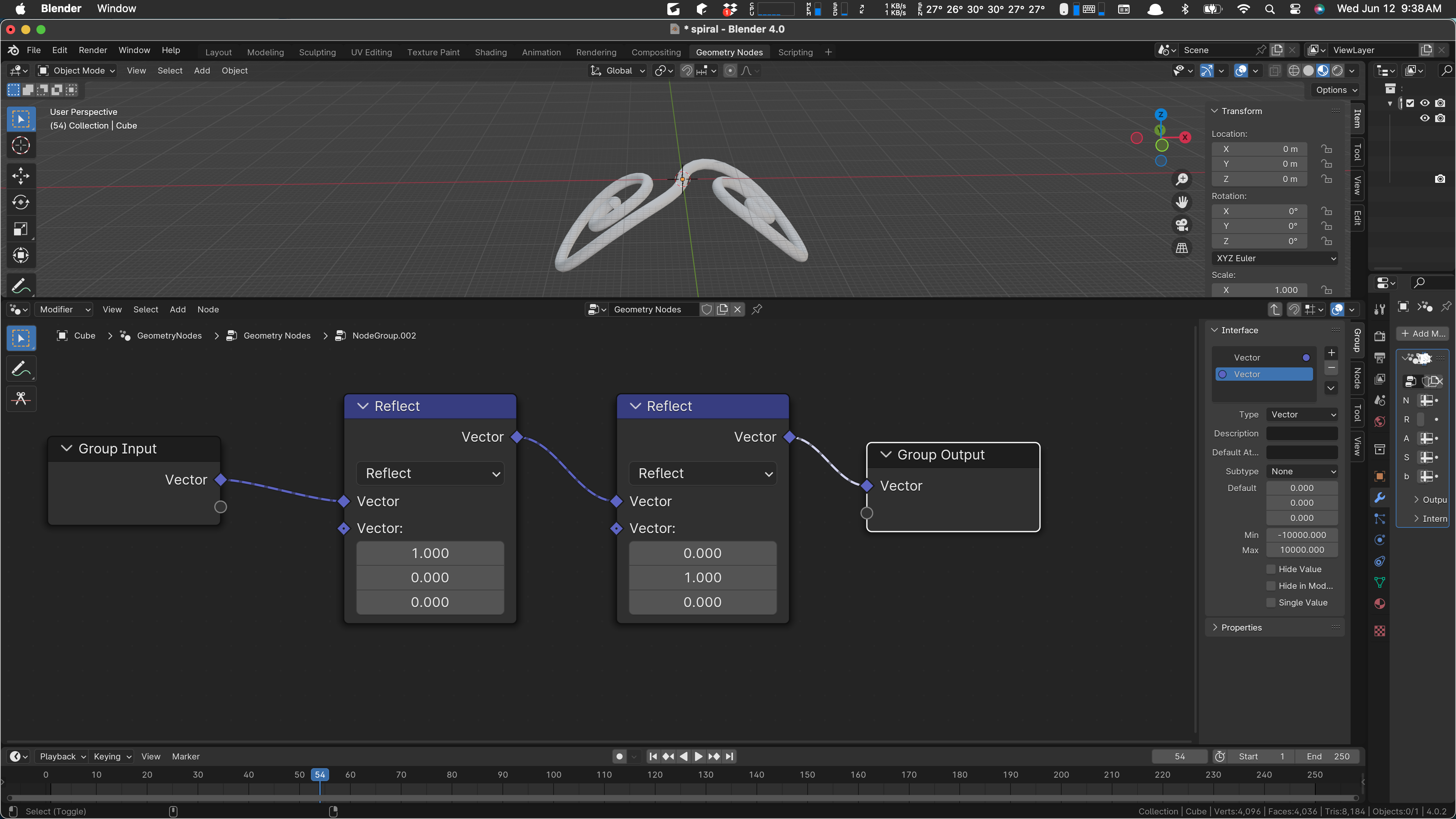
That didn’t work but I found Reflect. Reflecting on X and then Y does the trick:
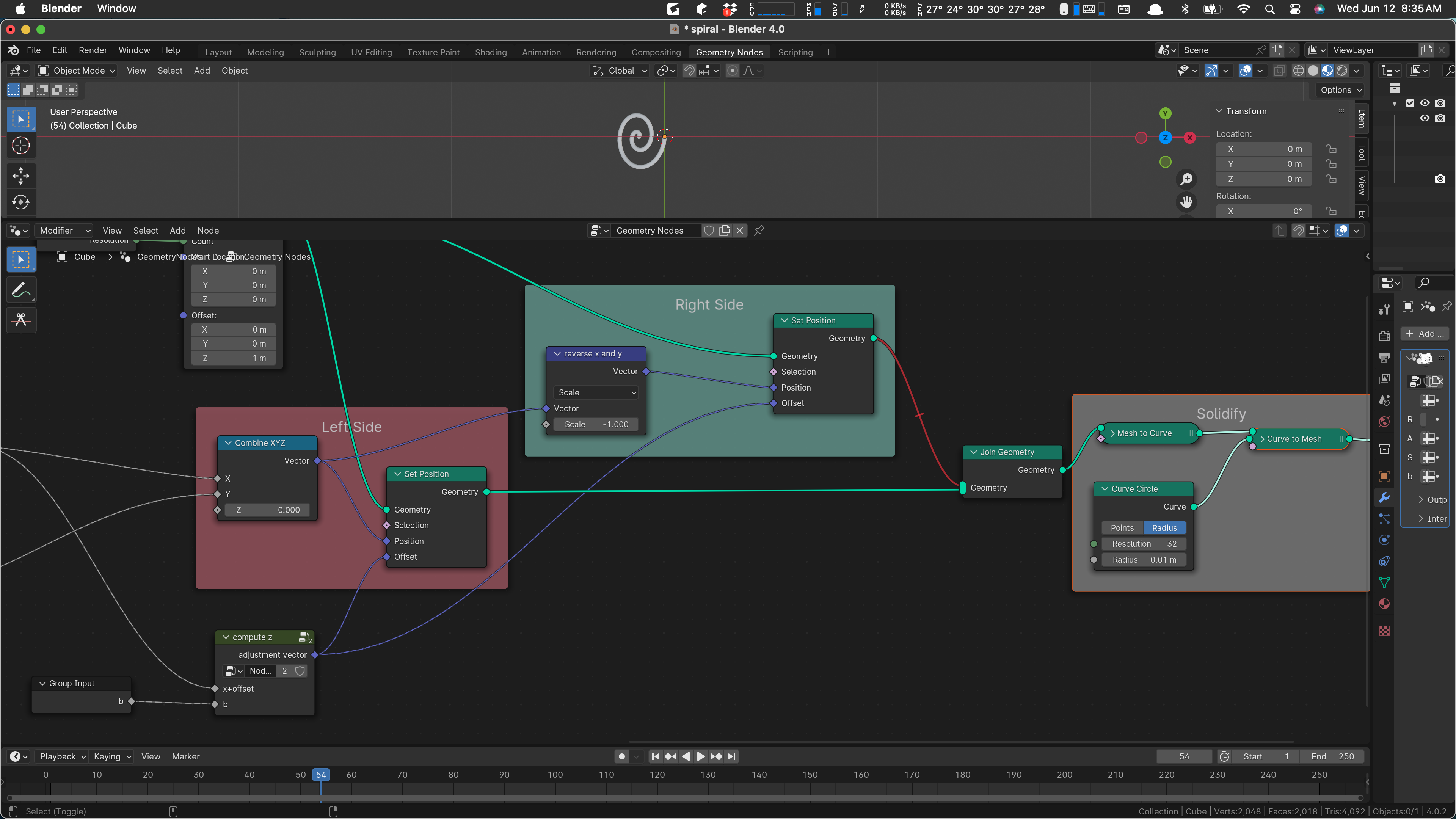
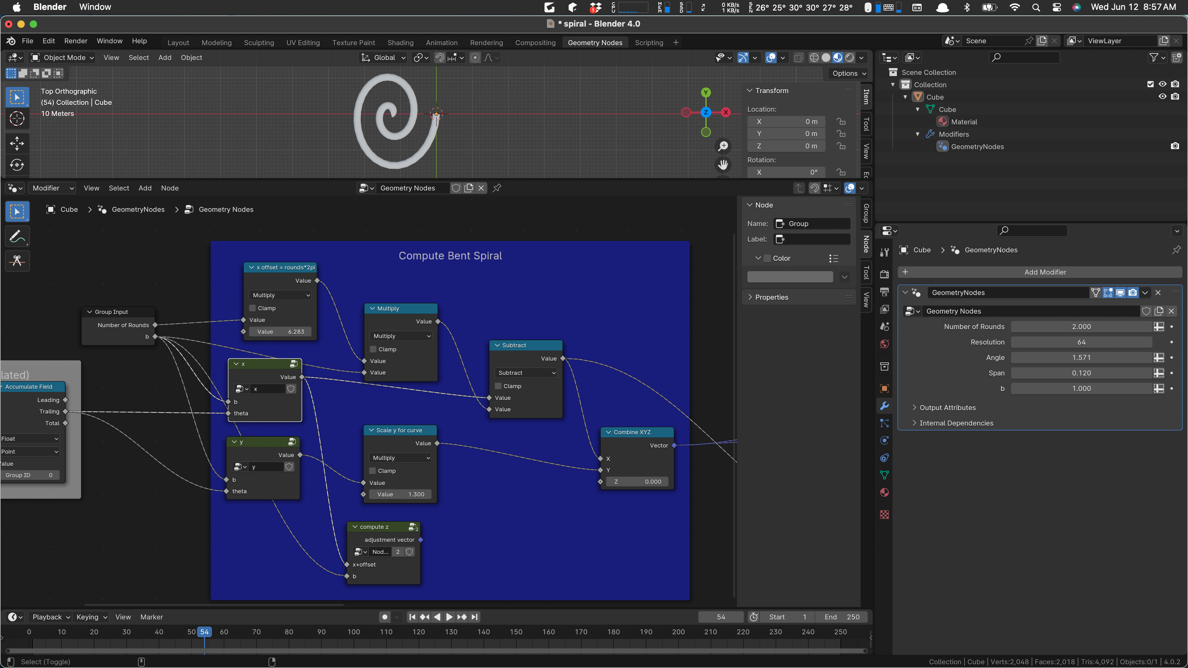
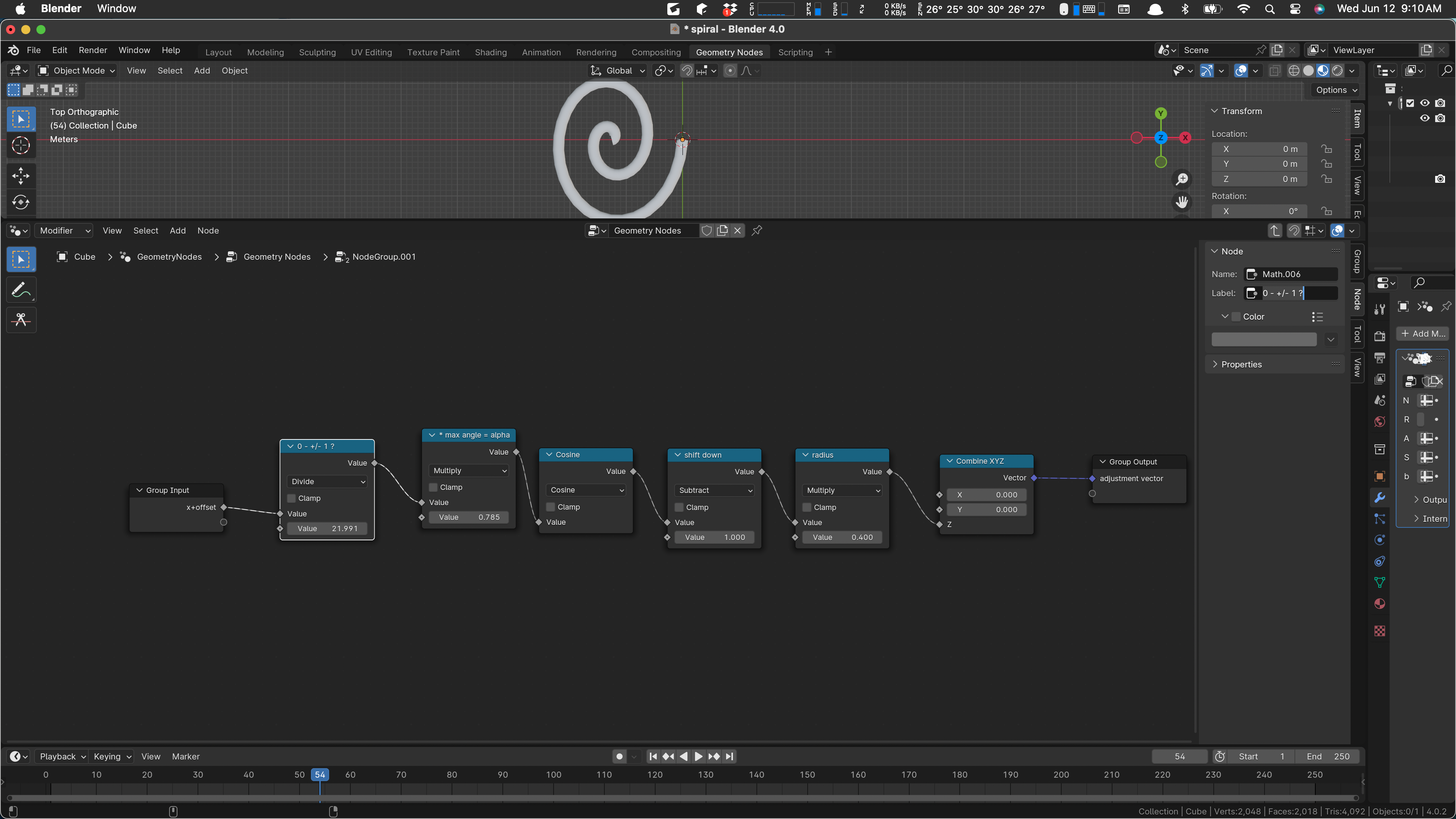
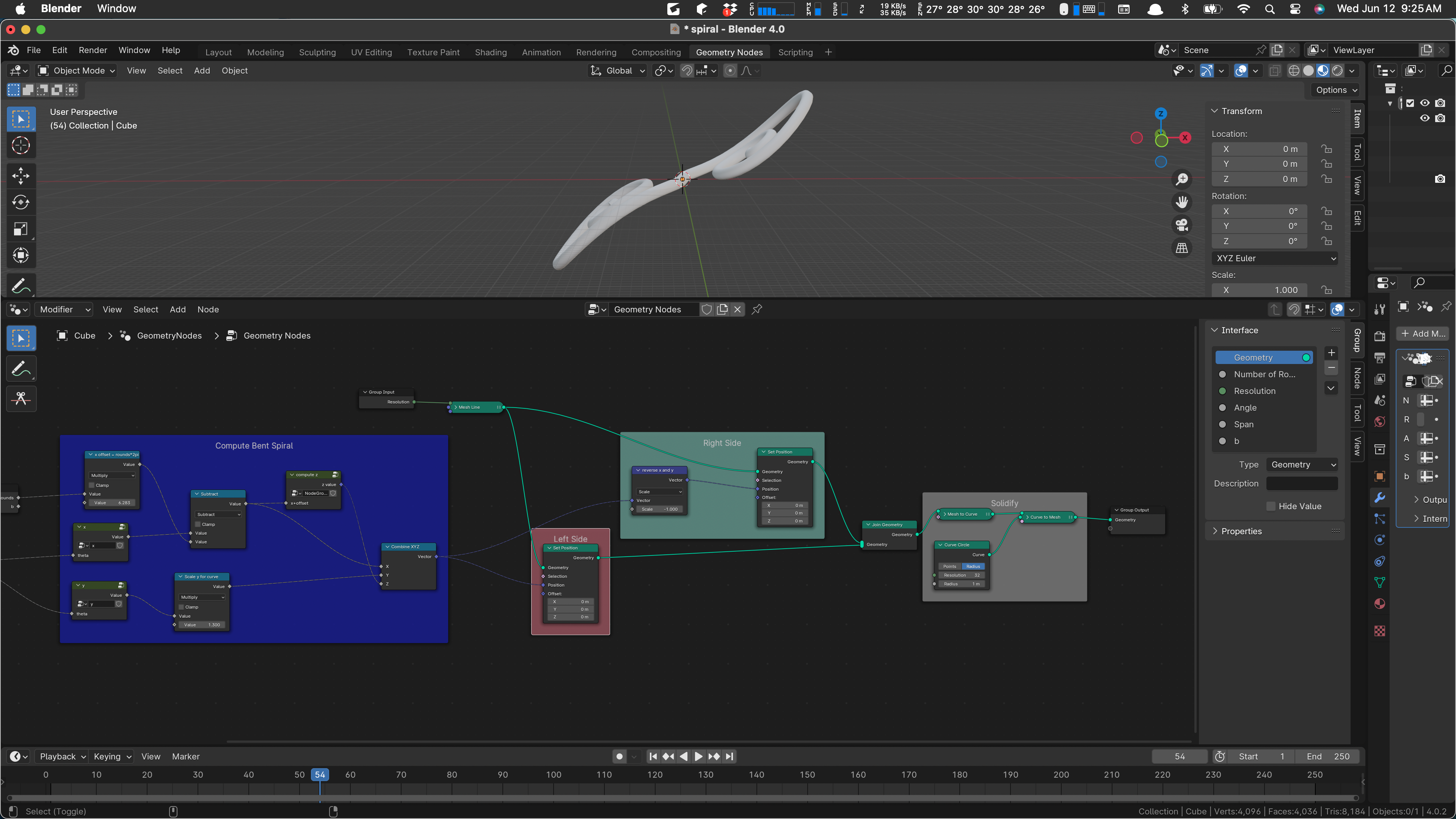
I’m tired. Better stop. I’ve still not been saving increments. Progress has been good. Here’s what we have now:
Left and right sides for details:
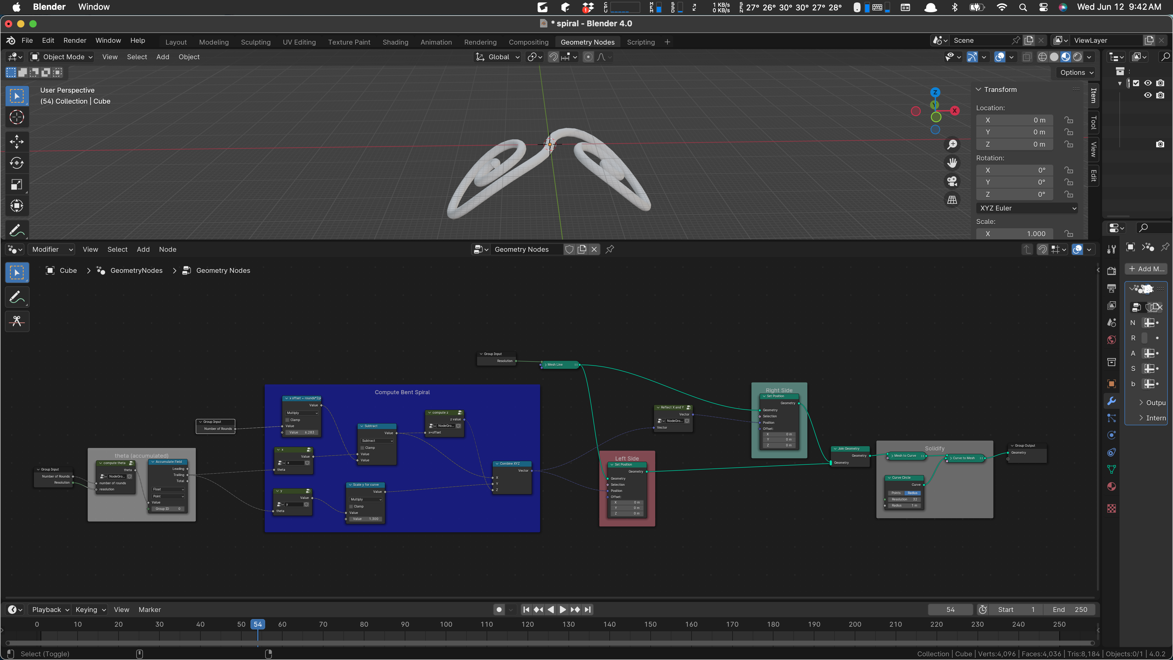
I think that’s improved. And it could be better. Maybe next time.