I’ve been reading a bit about linkages and forward kinematics. That leads, after a bounce or two to geometry and algebra.
- Revision
- Significant revisions or expansions will be indicated by showing the old text with strike-thru, and possibly with the new text italicized if the replacement isn’t otherwise clear. Smaller revisions may be italicized. Or not.
It appears that the official OK way to do forward kinematics is with some really interesting matrices, 4x4 and larger. But it also appears that while that’s the general way, a lot of what we need can be solved by “simple” geometric and algebraic reasoning.
- Forward Kinematics
- The calculation of the end position of a linkage from beginning to end, as opposed to “inverse kinematics”, where we calculate what the settings must be to position the end at a desired location. Forward makes more sense for a locomotive drive linkage, while inverse makes sense for positioning a robot arm to grab something.
We already have one example of such a problem. Our ConnectingRod has one end at a known position, because we know the position of the DriveWheel and its rotation, so we know the position of the attachment at that end. For the other end, we know that it lines along the line of the piston rod, but we do not know just where.
So far, I’ve solved this kind of “in my head” by use of the quadratic formula, in the simple case of a horizontal piston rod:
function ConnectingRod:center_delta(base_pos, wheel_end)
    local delta_y = base_pos.y - wheel_end.y
    local delta_x = - math.sqrt(self._length*self._length - delta_y*delta_y)
    return vector(delta_x, delta_y) / 2
end
The vector <delta_x, delta_y> is the position of the attachment to the piston rod, and I got the expression for delta_x by, well, algebra. I drew the right triangle with hypotenuse going from the wheel end to the piston rod end. Then they y coordinate was just the y coordinate of the horizontal piston rod and I solved the triangle for x.
- Note
- I believe that in practice the piston rod is always pointed directly at the center of the circle that the other end describes. If that’s the case, this solution can be “easily” generalized with a quick rotation. It might even be the case if the piston rod is not aligned with the center, but that would require more work before I’d be comfortable asserting it.
Anyway, I came up with that solution more by virtue of experienced intuition and knowing that x-squared plus y-squared equals d-squared. And yes, a tiny bit of algebra, but so little that I hardly noticed it.
There is another way that the same problem could be solved, using geometry and algebra.
Oops
I thought I was going to derive this code myself, but I didn’t, I got stuck, looked it up, found something probably “AI” generated, translated it to Lua and vectors, tested it, and refactored it. I’ll try to fully understand and explain it later today.
For now, here is a test that calculates the two possible points at distance 6.5 from the point(3,2) to the line defined by the points (7,3) and (11,8). For our purposes, we’ll want the one that is between the two points, but that’s not done yet in the code below.
_:test("another point on line at distance approach", function()
    local p0 = vector(3,2)
    local p1 = vector(7,3)
    local p2 = vector(11,8)
    local distance = 6.5
    local unit_direction = (p2 - p1):normalize()
    local t = (p0 - p1):dot(unit_direction)
    local p_closest = p1 + unit_direction*t
    local closest_distance = p0:dist(p_closest)
    local offset_distance = math.sqrt(distance*distance - closest_distance*closest_distance)
    local c1 = p_closest + unit_direction*offset_distance
    local c2 = p_closest - unit_direction*offset_distance
    _:expect(p0:dist(c1)).is(6.5, 0.01)
    _:expect(p0:dist(c2)).is(6.5, 0.01)
end)
The test runs, returning two points:
Feature: geometry calculations
<8.699707210426952, 5.12463401303369, 0>
<1.2027318139632919, -4.246585232545886, 0>
The first one checks out as the one that we want. I’ll finish this article later, including an explanation of the code, if not a derivation. What I have found (not created) is a closed-form that can be used to solve all our connecting rod problems given two points along the piston path. That’s worth having.,
Safe paths for now …
Back …
Let’s try to explain this code.
local unit_direction = (p2 - p1):normalize()
unit_direction is the unit vector in the direction from p1 to p2 along our target line.
local t = (p0 - p1):dot(unit_direction)
‘t’, by the geometric interpretation of the dot product, is the projection of one unit of our target line onto the vector from p1 to p0. Look at this triangle:
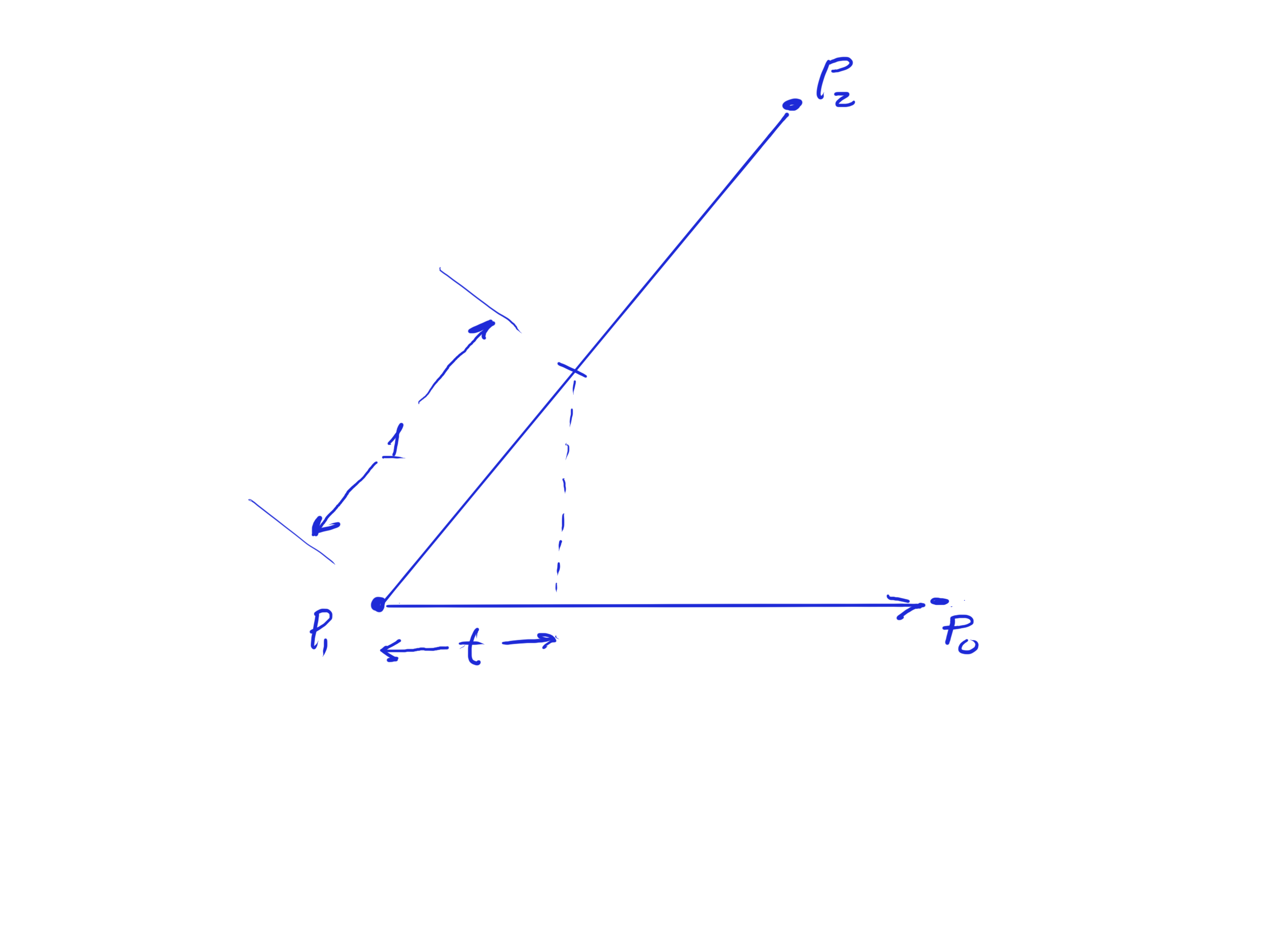
At the closest point of the line through p1 and p2, the angle shown in that triangle would, of course, be a right angle. TO make it a right angle, the point of intersection (t) needs to move exactly t units! The name of this variable should be distance_to_closest! I’ll rename it in what follows.
local distance_to_closest = (p0 - p1):dot(unit_direction)
local p_closest = p1 + unit_direction*distance_to_closest
p_closest is the point along p1-p2 that is closest to p0. (And the answer to my question above is that p_closest would be correctly computed as p1, so far so good. Ah, and that is the last use of t, so what follows should be OK.)
local closest_distance = p0:dist(p_closest)
local offset_distance = math.sqrt(distance*distance - closest_distance*closest_distance)
local c1 = p_closest + unit_direction*offset_distance
local c2 = p_closest - unit_direction*offset_distance
The rest is just Pythagorean Theorem. We construct a triangle from p0 to the closest point on p1-p2, and we want the hypotenuse to be our desired distance, so the distance along p1-p2 is square root of distance-squared minus closest-distance squared. There are two such points for the positive and negative root, on opposite sides of the closest point.
It would be nice if we could refactor this code a bit for clarity, but the fact that we need unit direction throughout makes that difficult. At least I don’t see an approach that seems to me to improve things.
Here is a picture that may help explain what’s going on:
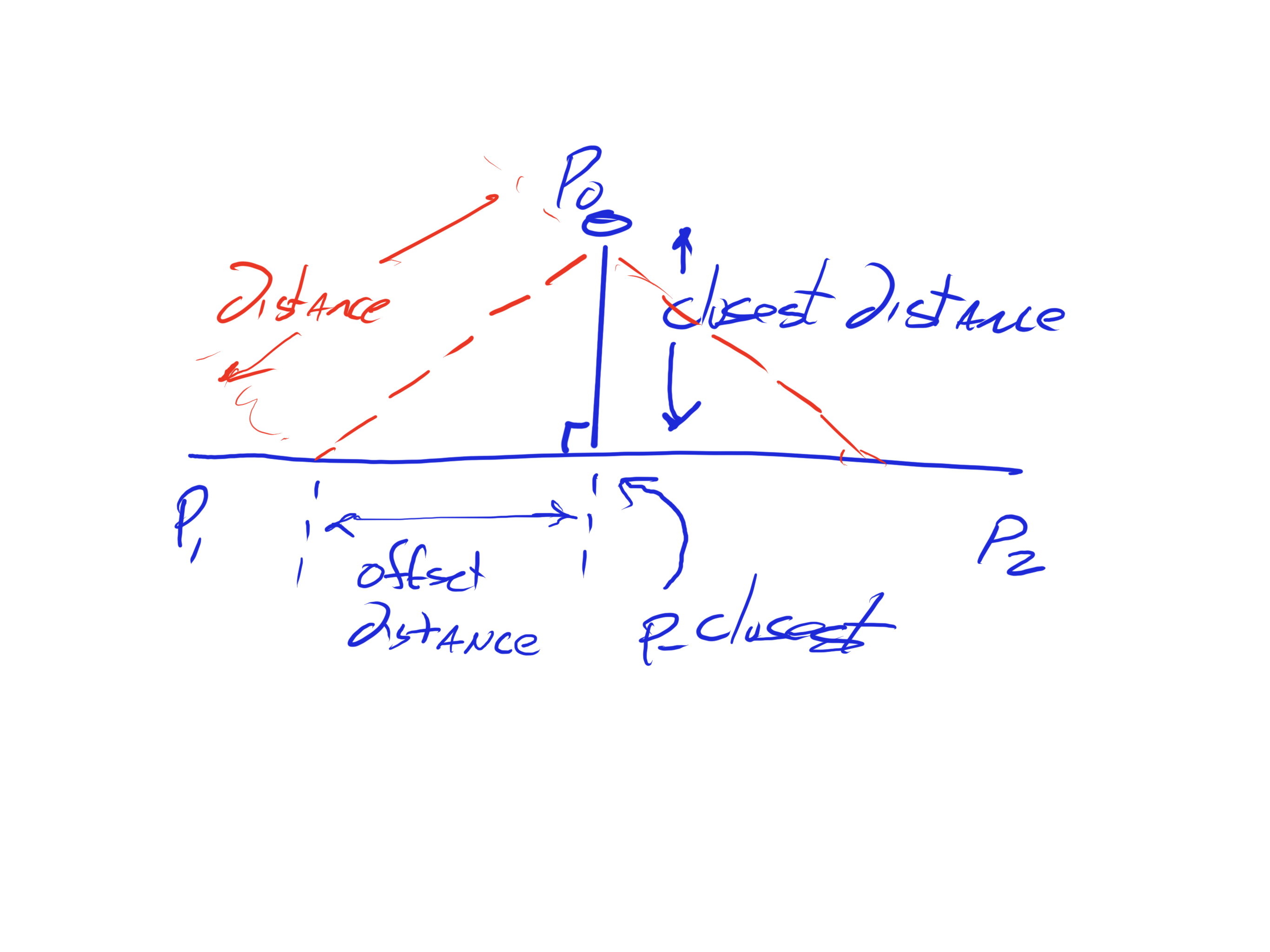
The key bits of magic here include:
- The dot product of p0-p1 onto the unit direction vector from p1 to p2 is the distance from p1 to the point of closest approach to p0 along p1-p2.
- The closest point to p0 on p1-p2 is
p1+unit_direction*distance_to_closest. This lets us construct a right triangle with hypotenuse the desireddistanceand a known altitude. - Then, by Pythagoras, the desired distance squared is equal to the closest distance from p0 to the line, squared, plus the offset distance along p1-p2 squared. Thus, the offset distance needed is plus-or-minus the square root of distance squared minus closest-distance squared.
- Added
- The key thing to remember here is the method for getting the point of closest approach of a line to an external point, the dot product thing. I feel sure that that will be useful at some time in the future. Maybe I should write a recipe.
So. What we have here is code that we can use to position the end of a ConnectingRod, far more generally than the current simple case we have now. Some time soon: finding points on a circular arc at a given distance from an external point. Useful in valve gear.
Safe paths!